Quick installation fuel dam

a fuel dam and quick technology, applied in the direction of power plant fuel tanks, spars/stringers, weight reduction, etc., can solve the problems of increasing the cost of the bracket installation process, requiring additional labor, and consuming a lot of tim

Active Publication Date: 2016-12-08
THE BOEING CO
View PDF7 Cites 43 Cited by
  • Summary
  • Abstract
  • Description
  • Claims
  • Application Information

AI Technical Summary

Problems solved by technology

The multiple brackets require eight or nine holes to be drilled to secure the brackets, which is extremely time consuming due to the number of brackets to be installed.
Additionally, the holes for the conventional brackets cannot be pre-drilled, but instead, need to be drilled at the time of wing assembly to ensure a proper fit, which requires an operator to work in confined spaces, thereby further increasing the cost of the bracket installation process.
This requires masking of surfaces of the wing ribs and brackets prior to application of protective treatments, which also requires additional labor.

Method used


Image

  • Quick installation fuel dam
  • Quick installation fuel dam
  • Quick installation fuel dam

Examples


Embodiment Construction

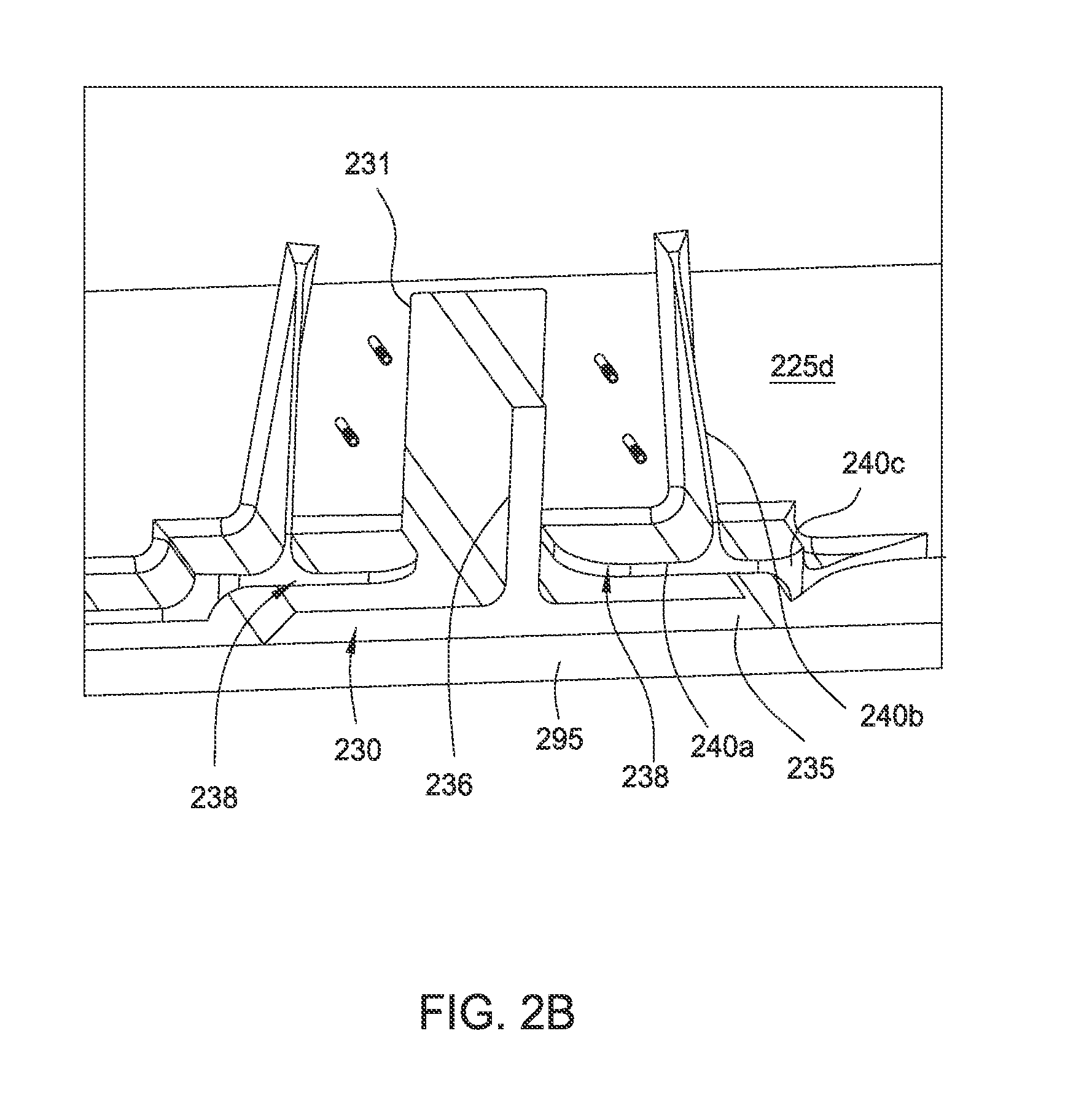
[0022]The disclosure generally relates to fuel dams having a single-piece or two-piece construction. In one example, a baffle fuel dam is a single piece having slotted holes sized and spaced to accommodate for tolerance variations during installation. The baffle fuel dams also include a base angle that allows installation at multiple locations. The disclosure also relates to tank boundary fuel dams that include a two-piece configuration which incorporates slotted holes to accommodate tolerance variations and that are sized / spaced for different installation locations. The tank boundary fuel dams may also include a base angle that allows installation at multiple locations.

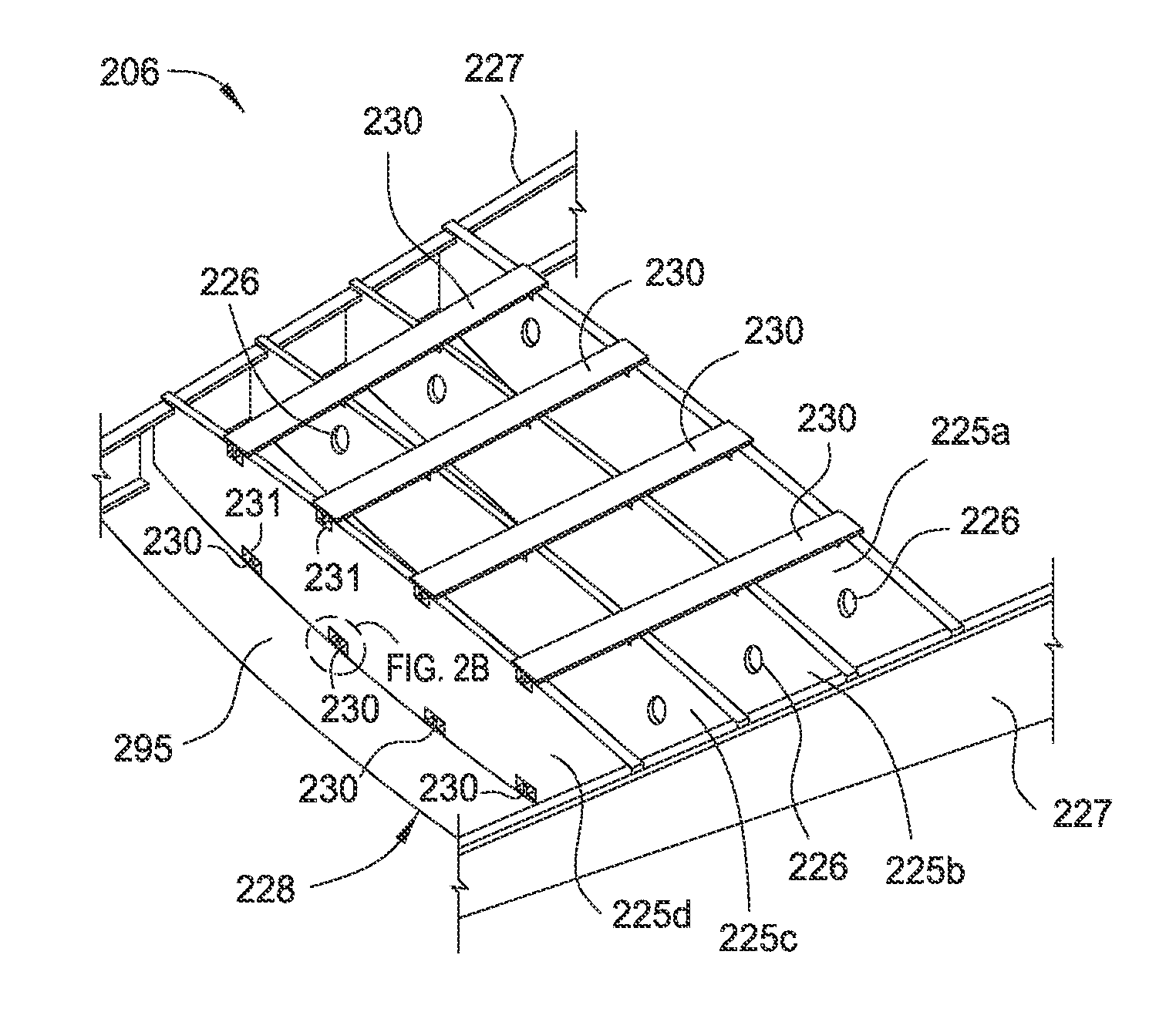
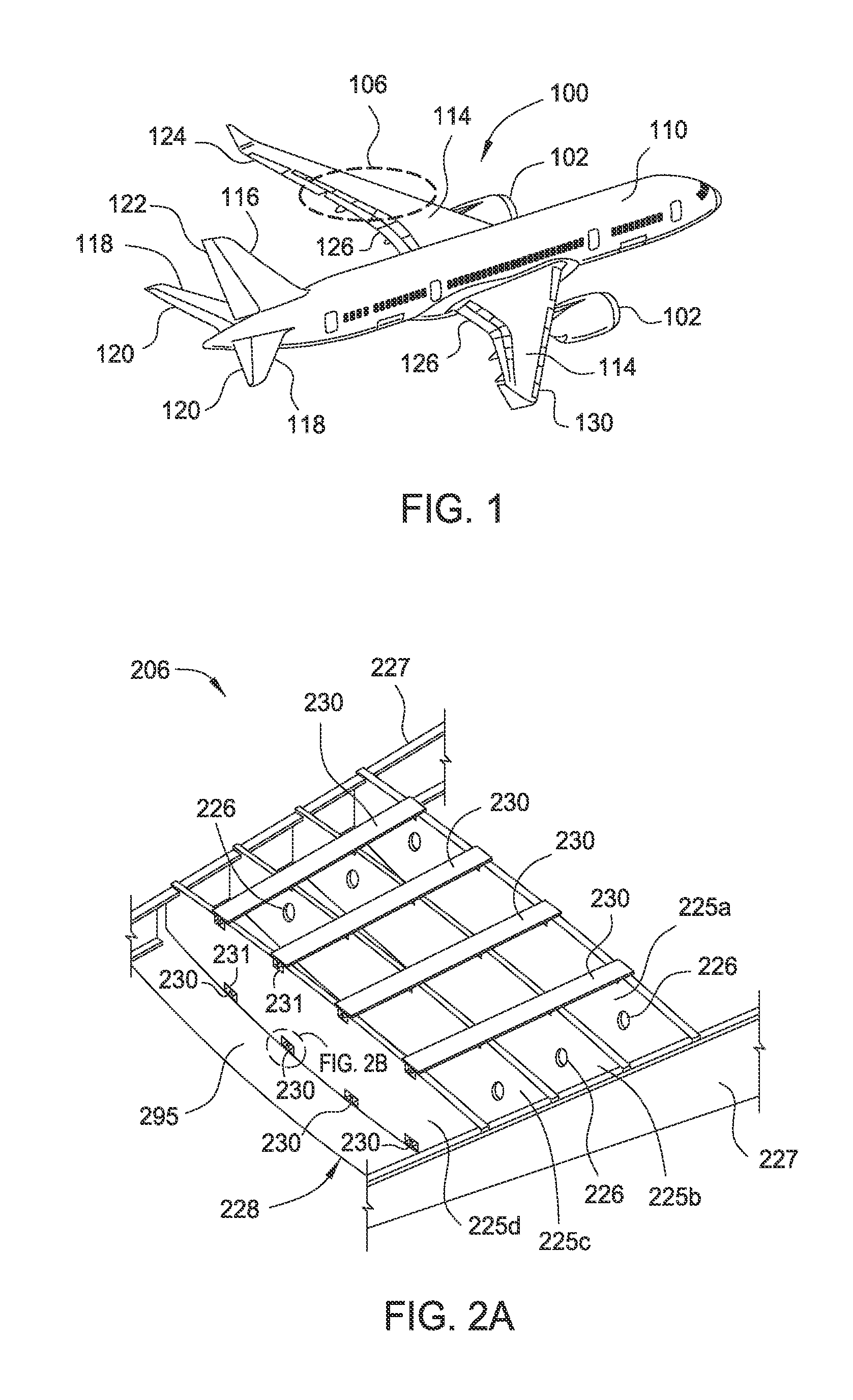
[0023]FIG. 1 is a perspective view of an aircraft 100 according to one aspect of the disclosure. The aircraft 100 includes a fuselage 110 for holding passengers and / or cargo. Two wings 114, which provide the lift needed to fly the aircraft 100, are coupled to opposite sides of the fuselage 110. A vertical stabilizer ...


PUM


Abstract

The disclosure generally relates to baffle fuel dams and tank boundary fuel dams having a single-piece or two-piece construction. In one example, a baffle fuel dam is a single piece having slotted holes sized and spaced to accommodate for tolerance variations during installation. The baffle fuel dams also include a base angle that allows installation at multiple locations. The disclosure also relates to tank boundary fuel dams that include a two-piece configuration which incorporates slotted holes to accommodate tolerance variations and that are sized / spaced for different installation locations. The tank boundary fuel dams may also include a base angle that allows installation at multiple locations.

Description

BACKGROUNDField[0001]Embodiments of the present disclosure generally relate to fuel dams, such as fuel dams for restricting fuel flow inside of aircraft wing tanks.Description of the Related Art[0002]Fuel tanks in some aircraft are contained within the aircraft structure that has been sealed to allow fuel storage. An example of this type is the “wet wing” commonly used in larger aircraft. Since these fuel tanks are part of the aircraft structure, the tanks are designed to meet the structural integrity requirements as well as function of fuel tanks. Large transport aircraft may store fuel in the wings and / or tail of the aircraft. This configuration reduces the weight and complexity as compared to a bladder system.[0003]Typical wing construction includes a plurality of ribs coupled to one or more spars of a wing. The ribs and spars may then be covered with wing panels, which may include a skin having a string coupled thereto as a stiffening member, to provide an external shape to the ...

Claims


Application Information

Patent Timeline
Patent Type & Authority Applications(United States)
IPC IPC(8): B64D37/08B64C3/34B64C3/18
CPCB64D37/08B64C3/182B64C3/34B64C3/187B64C3/185Y02T50/40
Inventor PEREZ DIAZ, FERNANDO L.TANNER, RICHARDRODRIGUEZ, BRENDAMARI
Owner THE BOEING CO
Why Eureka
Try Eureka