Mounting device for installation against a substantially horizontal surface and use thereof

a technology for mounting devices and substantially horizontal surfaces, which is applied in the direction of rod connections, machine supports, fastening devices, etc., can solve the problems of difficult installation of suspended ceilings, inability to adjust the appropriate amount of tension between end plugs, and a large amount of work

Inactive Publication Date: 2016-12-08
LABFLEX AS
View PDF4 Cites 0 Cited by
  • Summary
  • Abstract
  • Description
  • Claims
  • Application Information

AI Technical Summary

Benefits of technology

[0010]By using two parallel assembly units, good stability is obtained in the horizontal direction, thus providing a good suspension unit for service bridges etc. By using a U-shaped fitting comprising the two parallel tubes, which tubes are open at both ends, and because the tubes are connected to each other by a crossbar, increased stability is achieved. The crossbar is preferably a T profile which gives the structure considerable stability. Service bridges etc. are therefore secured to the crossbar. Thus by linking the two parallel suspended rod-shaped elements together at the first fitting formed as a U fitting, a simple attachment facility is provided for installing service bridges etc., whilst at the same time rendering the structure rigid and stable.
[0023]In a further exemplary embodiment according to the present invention, the threaded rod is secured to the upper tube above the wedging surface by means of a dolly and an end plug with a central hole for a support rod is threaded to the termination of the upper tube opposite the wedging surface, where the support rod connects the dolly to the support arm so that the end plug and the support arm cam be clamped against or away from each other due to the threaded engagement of the end plug with the termination of the upper tube without affecting the locking together of the wedging tubes to secure the hollow tubes in a given position.
[0024]This embodiment ensures, in particular, that the clamping together of the wedging tubes remains independent of the fastening to the ceiling rail. When the wedging tubes are clamped together, the tension in the threaded rod is located between the lower lock nut and the dolly, and the clamping does not therefore affect the fastening between the support arm and the ceiling rail. This makes it possible to screw the end plug down a little, thereby reducing the tension between the end plug and the support arm so that the support arm, together with the assembly unit, can be moved along the rail or moved to another rail. It also makes it possible to slacken the nut at the end of the lower wedging tubes in order to adjust the distance of the U-shaped fitting from the ceiling, so that the levelling of several fittings can be finely adjusted without loosening them from their positions against the ceiling.
[0025]It may also be appropriate for the end plug to be provided with a transverse setscrew which enables the end plug to be locked in a given position. This provides a greater guarantee that the end plug will not loosen in time from its clamped position against the rail.

Problems solved by technology

However, the ceiling is often sloping, thus a good deal of work is required to ensure that the fittings are correctly installed and that service bridges and wall cabinets do not hang at an angle.
Moreover, it may be difficult to have the suspended ceiling erected when the fittings have been installed, and their adequate adjustment is therefore impossible since the suspended ceiling conceals the attachment of the fittings to the load bearing ceiling.
The possibilities of adjusting the existing ceiling suspensions are therefore extremely limited.

Method used


Image

  • Mounting device for installation against a substantially horizontal surface and use thereof
  • Mounting device for installation against a substantially horizontal surface and use thereof
  • Mounting device for installation against a substantially horizontal surface and use thereof

Examples


Embodiment Construction

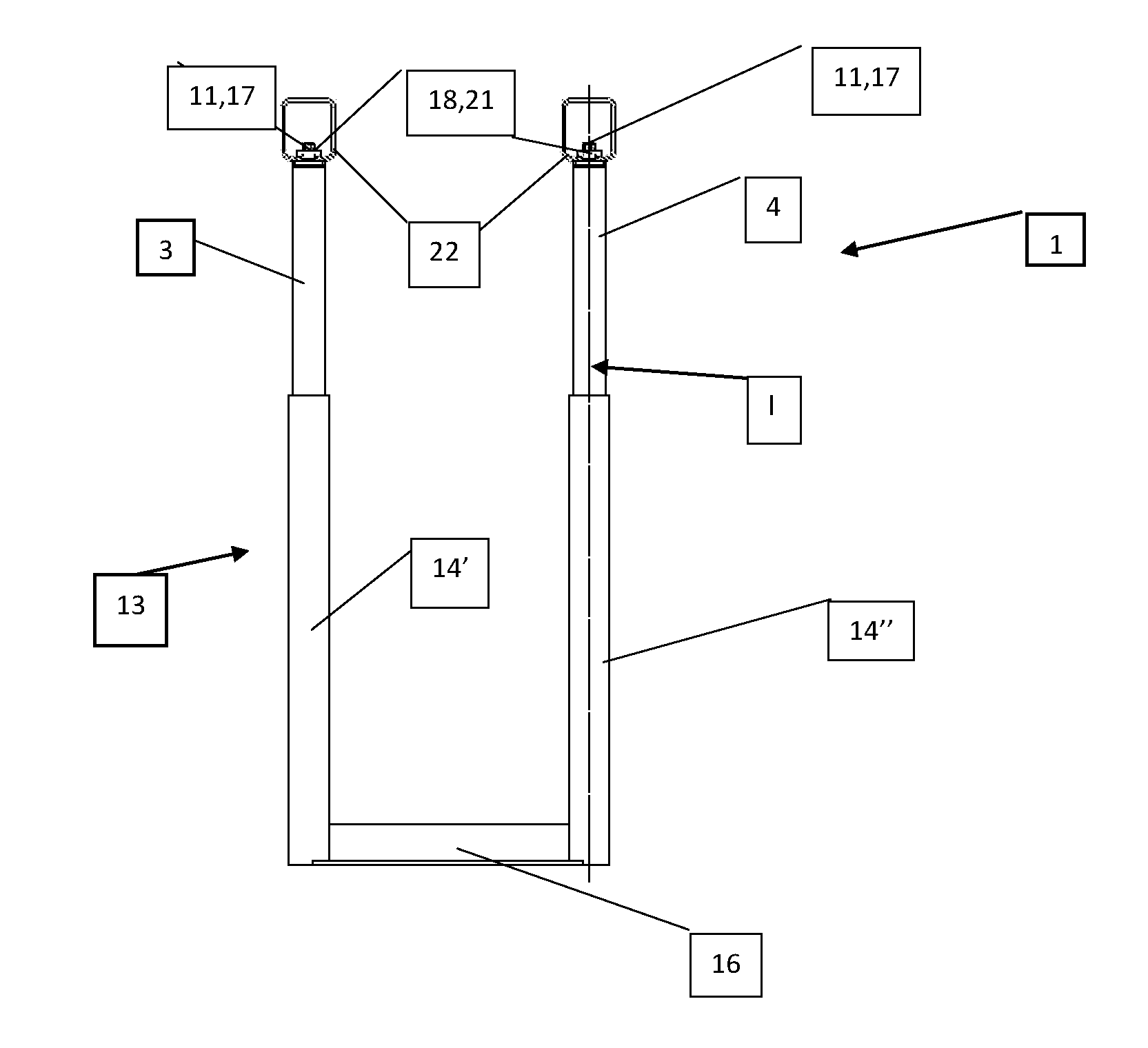
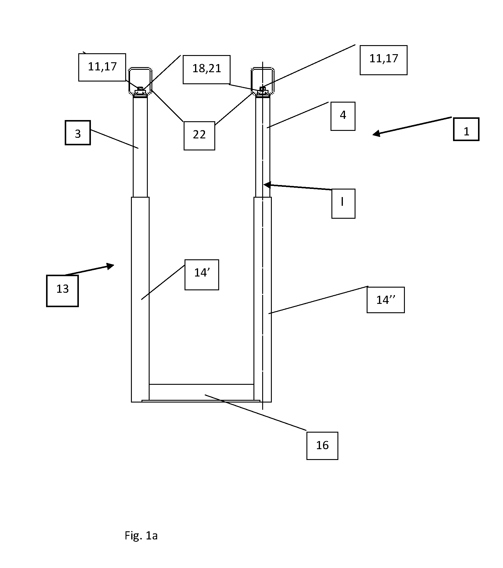
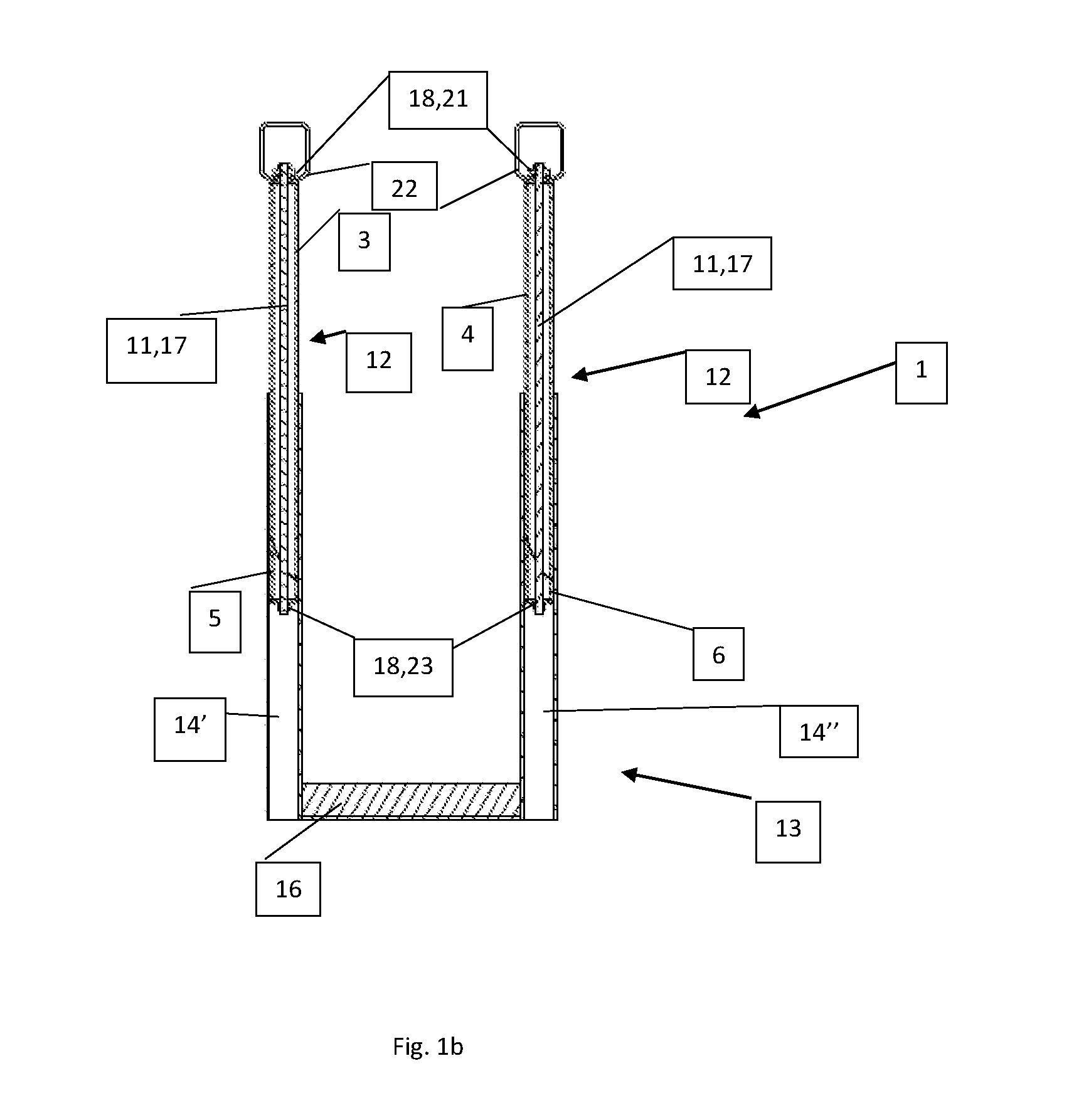
[0041]FIG. 1a shows an embodiment of an assembly unit 1 according to the invention, and FIG. 1b shows the same in cross-section only. The assembly unit comprises 2 essentially parallel hollow tubes: a first upper tube 3 and a second upper tube 4, as well as two lower tubes: a first lower tube 5 and a second lower tube 6. All the tubes are so-called wedging tubes, which means that one end face on each tube is wedge-shaped and flat so that when the upper wedging tubes are clamped together with the lower wedging tubes, it is the oblique surfaces on the respective tubes which are clamped against and slide towards each other.

[0042]Wedging surface 7 of the first upper tubes 3 faces towards wedging surface 8 of the first lower tube 5 and wedging surface 9 of the second upper tube 4 faces towards wedging surface 10 of the second lower tube 6, as shown in FIG. 2a, b.

[0043]Assembly unit 1 also has a fastening mechanism 11 for clamping the first lower tube 5 against the first upper tube 3, an...


PUM


Abstract

An assembly unit (1) for mounting in a load bearing ceiling (2), having a first upper tube (3) and a first lower tube (5), both of which are wedging tubes whose wedge-shaped ends (7, 8) face each other. The assembly unit (1) has a fastening mechanism (11) for clamping the first lower tube (5) to the first upper tube (3) to form a rod-shaped element (12). The assembly unit (1) also has a first fitting (13) which has a hollow tube (14′), which tube (14′) is designed fully or partially to enclose the rod-shaped element (12). The fastening mechanism locks together the wedging tubes (3, 5) and secures the hollow tube (14′) in a given position in relation to the rod-shaped element (12).

Description

CROSS-REFERENCE TO RELATED APPLICATIONS[0001]This application claims priority to Danish Appl. No. PA 2015 70337 filed Jun. 3, 2015, which is hereby incorportated by reference in its entirety.TECHNICAL FIELD[0002]The invention relates to an assembly unit for mounting on an essentially horizontal surface such as a load bearing ceiling, which assembly unit comprises a first and a second hollow tube, wherein both tubes are divided into an upper tube and a lower tube, which upper tube and lower tube are each wedging tubes whose wedge-shaped ends face each other so that the wedging surface of the upper tube faces away from the wedging surface of the lower tube, and wherein the assembly unit further comprises a fastening mechanism in the first and in the second tube for clamping together the wedging surfaces of the lower tubes and the wedging surfaces of the first upper tubes to produce rod-shaped elements.BACKGROUND[0003]When service bridges and wall cabinets are to be assembled in labora...

Claims


Application Information

Patent Timeline
Patent Type & Authority Applications(United States)
IPC IPC(8): F16M13/02A47B95/00
CPCA47B95/008F16M13/027F16B7/025F16B7/1463
Inventor KIRKEBY, KURT NEDERGAARD
Owner LABFLEX AS
Why Eureka
Try Eureka