Exercise device having sled or wheelbarrow configuration

a technology of exercise equipment and sleds, which is applied in the direction of gymnastic exercise, sport apparatus, weights, etc., can solve the problems of affecting the user's return trip, unable to carry the typical material carrying bucket or hopper, and exercise wheelbarrows suffering the disadvantages of weight adjustment as their exercise sled brethren, so as to achieve quick and easy conversion

Active Publication Date: 2016-12-15
POWERBLOCK HLDG
View PDF6 Cites 16 Cited by
  • Summary
  • Abstract
  • Description
  • Claims
  • Application Information

AI Technical Summary

Benefits of technology

[0011]One aspect of this invention relates to an exercise device which comprises a frame having a support surface engaging portion that permits the frame to move forwardly over the support surface as a user pushes the frame forwardly using at least one pair of handles provided on the frame. A carriage is provided on the frame configured to support at least one exercise weight member thereon for adding mass to the frame. The carriage is selectively movable on the frame by the user into different fore-and-aft positions on the frame to vary the resistance to pushing that the user must overcome in order for the user to push the frame forwardly. The carriage and the frame have a cooperable lock disposed therebetween for retaining the carriage in one of the positions selected by the user.
[0012]Another aspect of this invention relates to an exercise device which comprises a frame having a front end and a rear end. Two laterally spaced handles are carried on the frame adjacent the rear end of the frame. The handles are selectively repositionable by a user on the frame from a first generally horizontal orientation to a second generally vertical orientation and vice versa. At least one support surface engaging wheel is carried on the frame adjacent the front end of the frame with the at least one wheel being rotatable about a substantially horizontal axis of rotation to permit rolling the frame over a support surface. At least one support surface engaging, fore-and-aft extending skid is provided on the frame. At least one exercise weight member is carried on the frame for adding mass to the frame. The at least one skid is positioned relative to the at least one wheel such that the at least one skid is lifted up out of contact with the support surface while the at least one wheel remains in contact with the support surface when the handles are positioned in their first generally horizontal orientation and a user grips the handles and elevates the rear end of the frame by lifting up on the handles to incline the frame downwardly towards the front end of the frame in the manner of a wheelbarrow such that the user is thereafter able to push forwardly on the handles to roll the frame forwardly over the support surface in the manner of a wheelbarrow. In addition, the at least one skid remains in contact with the support surface when the handles are positioned in their second generally vertical orientation such the user is thereafter able to push forwardly on the handles to slide the frame forwardly over the support surface in the manner of a sled. The frame may be quickly and easily converted from use in the wheelbarrow manner to use in the sled manner and vice versa depending upon whether the user has installed the handles in their first generally horizontal orientation on the frame or in their second generally vertical orientation on the frame, respectively.

Problems solved by technology

In addition, if a user selects a very heavy total weight for the sled and then moves the sled a considerable distance over the support surface, the user might decide that the same very heavy total weight is now too much for the user to move over the return trip back to the starting point due to the effort the user expended in the first half of the trip.
Unfortunately, this leaves the offloaded weight plates at some distance away from the starting point and requires the user to subsequently go and retrieve them.
Such exercise wheelbarrows lack the typical material carrying bucket or hopper found on the types of wheelbarrows found in lawn and garden stores.
To the extent that exercise wheelbarrows simply use pegs or pins for carrying a selected number of stacked weight plates in order to adjust the total weight of the wheelbarrow, exercise wheelbarrows suffer the same weight adjustment disadvantages as their exercise sled brethren.
However, the manner of construction of the Agate device and the nature of the conversion is unduly complicated and somewhat cumbersome.
These separate handles are prone to being lost on unavailable when needed.
In addition, the Agate device uses the traditional peg or pin / stacked weight plate method of total weight adjustment and thus suffers from the weight adjustment disadvantages discussed above.

Method used


Image

  • Exercise device having sled or wheelbarrow configuration
  • Exercise device having sled or wheelbarrow configuration
  • Exercise device having sled or wheelbarrow configuration

Examples


Embodiment Construction

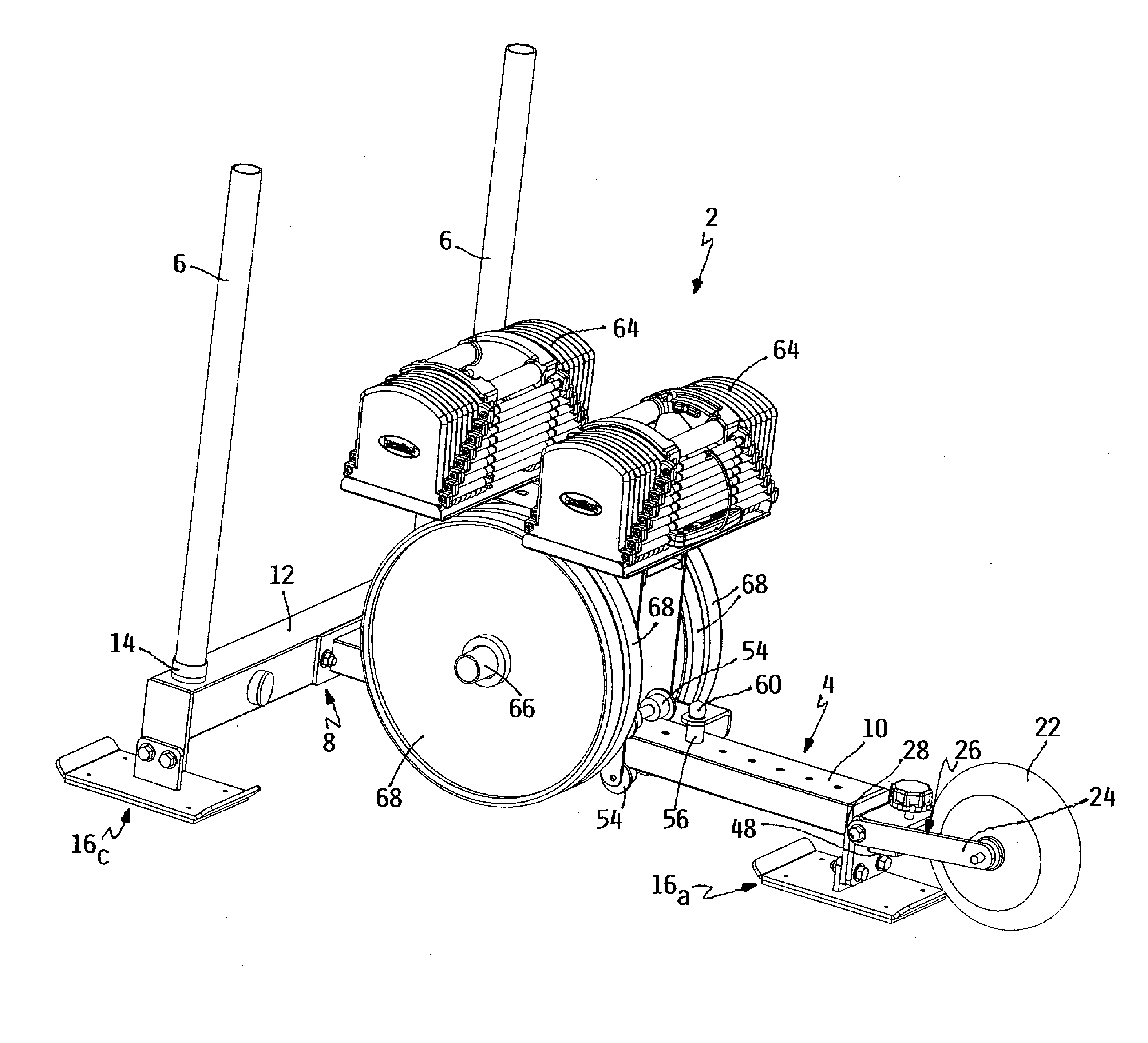
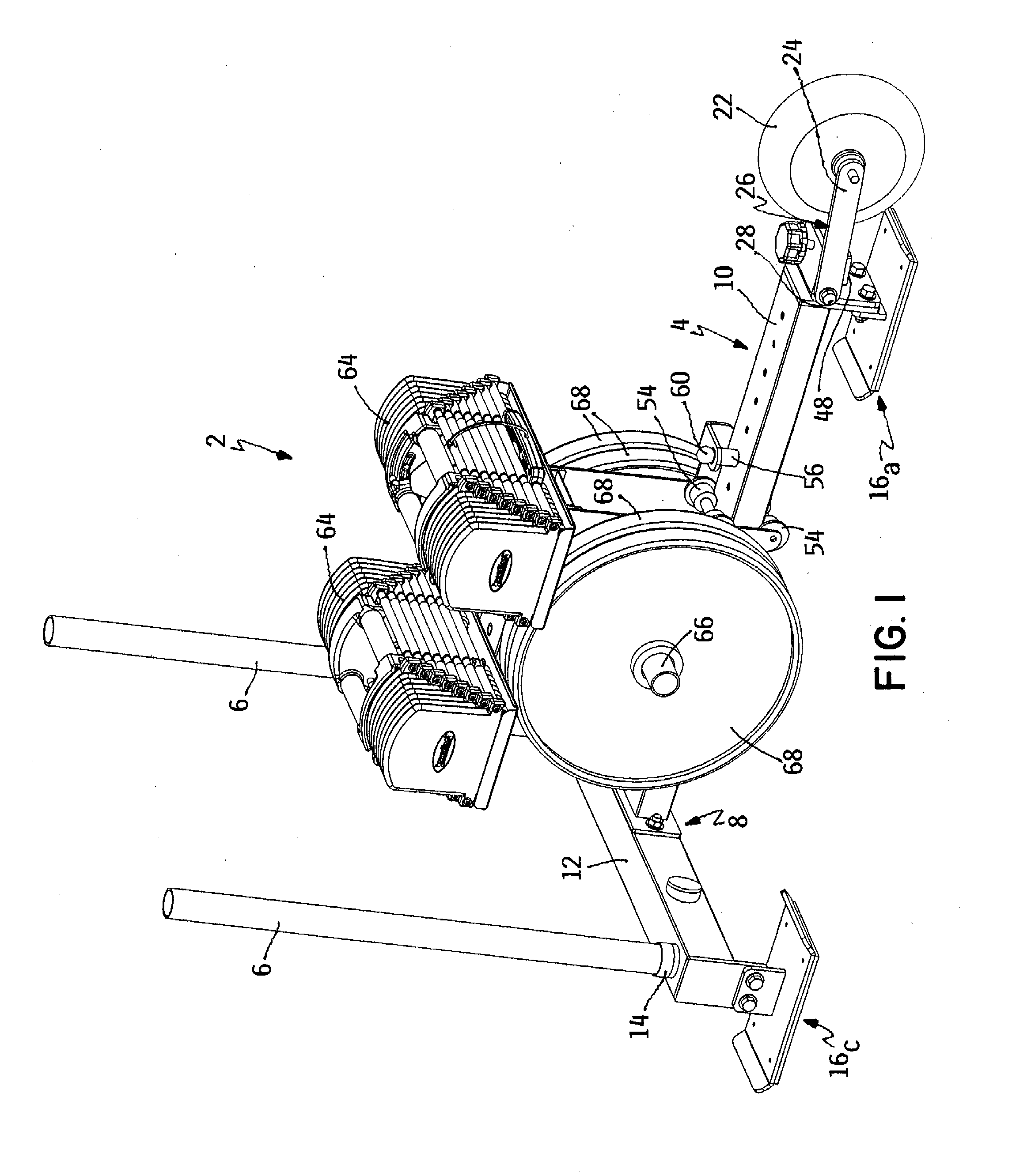
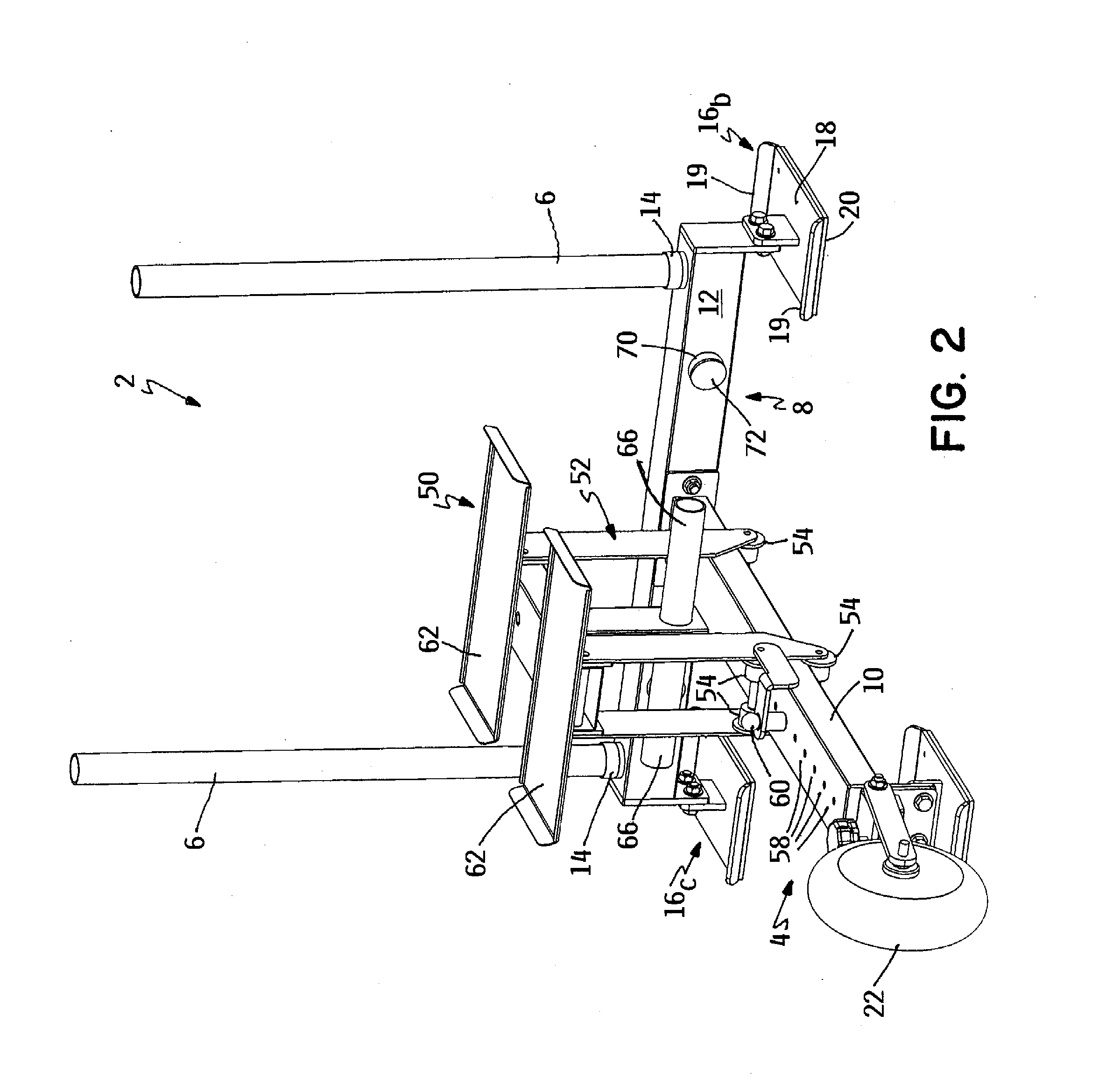
[0020]A first embodiment of an exercise device according to this invention is illustrated in the drawings generally as 2. FIGS. 1-3 depict device 2 set up for use as an exercise sled 4. Device 2 includes a pair of laterally spaced handles 6 that can be gripped by a user when device 2 is being used by the user for exercising. Handles 6 can be quickly and easily repositioned from a substantially vertical orientation to a substantially horizontal orientation to convert device 2 from sled 4 to an exercise wheelbarrow 5 without the need for any additional parts or separate specially shaped handle assemblies. FIG. 4 depicts device 2 after device 2 has been converted into wheelbarrow 5.

[0021]Device 2 includes a T-shaped frame 8 having a fore-and-aft extending, hollow, tubular rail 10. Rail 10 is fixed at one end to a hollow, tubular cross member 12 that extends laterally beyond either side of rail 10 to form the T-shape. Frame 8 is oriented generally horizontally with rail 10 and cross mem...


PUM


Abstract

An exercise device having a sled or wheelbarrow configuration comprises a frame that is pushed across a support surface by a user. The frame carries a wheel that movably supports the frame in the wheelbarrow configuration and at least one skid that movably supports the frame in the skid configuration. A pair of handles is selectively repositionable on the frame from a vertical orientation used in the sled configuration and a horizontal orientation used in the wheelbarrow configuration to quickly and easily convert the device between its different configurations. The frame has a carriage that supports a plurality of exercise weight members with the carriage being movable in a fore-and-aft direction on the frame for changing the effort required from the user to push the frame.

Description

TECHNICAL FIELD[0001]This invention relates generally to exercise equipment and, more particularly, to sled and wheelbarrow type devices that are manually moved by a user over a substantially horizontal support surface, such as the ground or a floor, to thereby build strength.BACKGROUND OF THE INVENTION[0002]Exercise devices are known, often popularly called “sleds”, which comprise a ground engaging frame that the user moves over a substantially horizontal support surface, such as the ground or a floor, to build leg and upper body strength. In many cases, such a sled includes handles which the user, who is standing behind the sled, grips and pushes forwardly against to push the sled over the support surface in a generally forward direction of motion. In other cases, the sled includes some type of harness which the user, who is now standing ahead of the sled, wears to pull or drag the sled behind the user in a generally forward direction of motion as the user moves forwardly. In most...

Claims


Application Information

Patent Timeline
Patent Type & Authority Applications(United States)
IPC IPC(8): A63B21/06A63B22/20A63B21/22A63B21/00A63B21/072
CPCA63B21/06A63B21/0004A63B21/0726A63B22/20A63B21/4043A63B21/4035A63B21/22A63B21/0615A63B21/0618A63B21/0724A63B21/16A63B23/03516A63B23/03575A63B23/04A63B23/047A63B23/12A63B2208/0204A63B2225/09A63B2225/093A63B21/00065A63B21/00072A63B21/00061A63B21/00069A63B21/4005B62B1/18
Inventor TOWLEY, MATTSON K.
Owner POWERBLOCK HLDG
Why Eureka
Try Eureka