
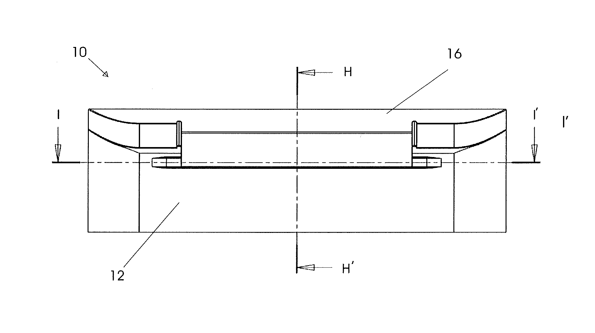
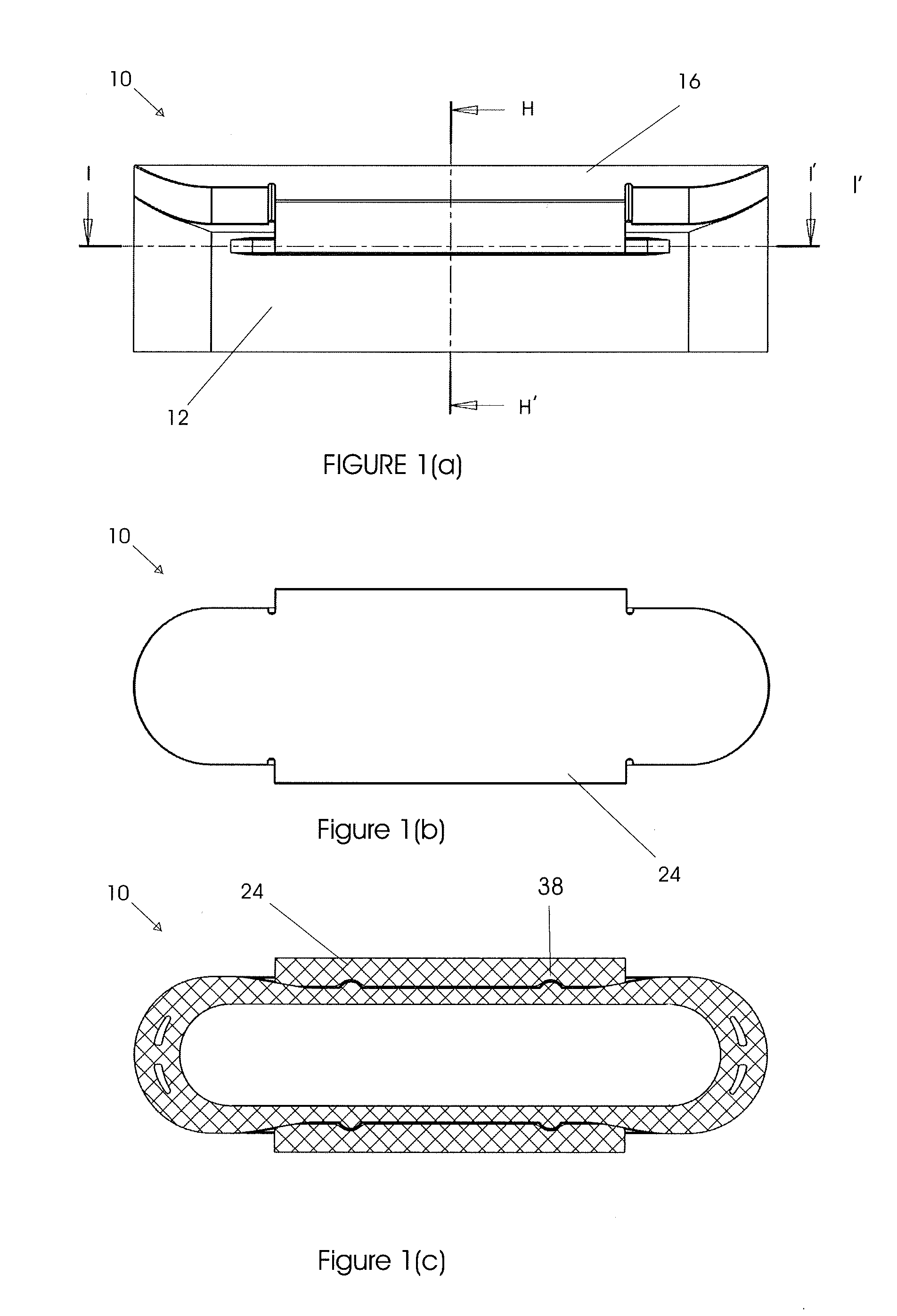
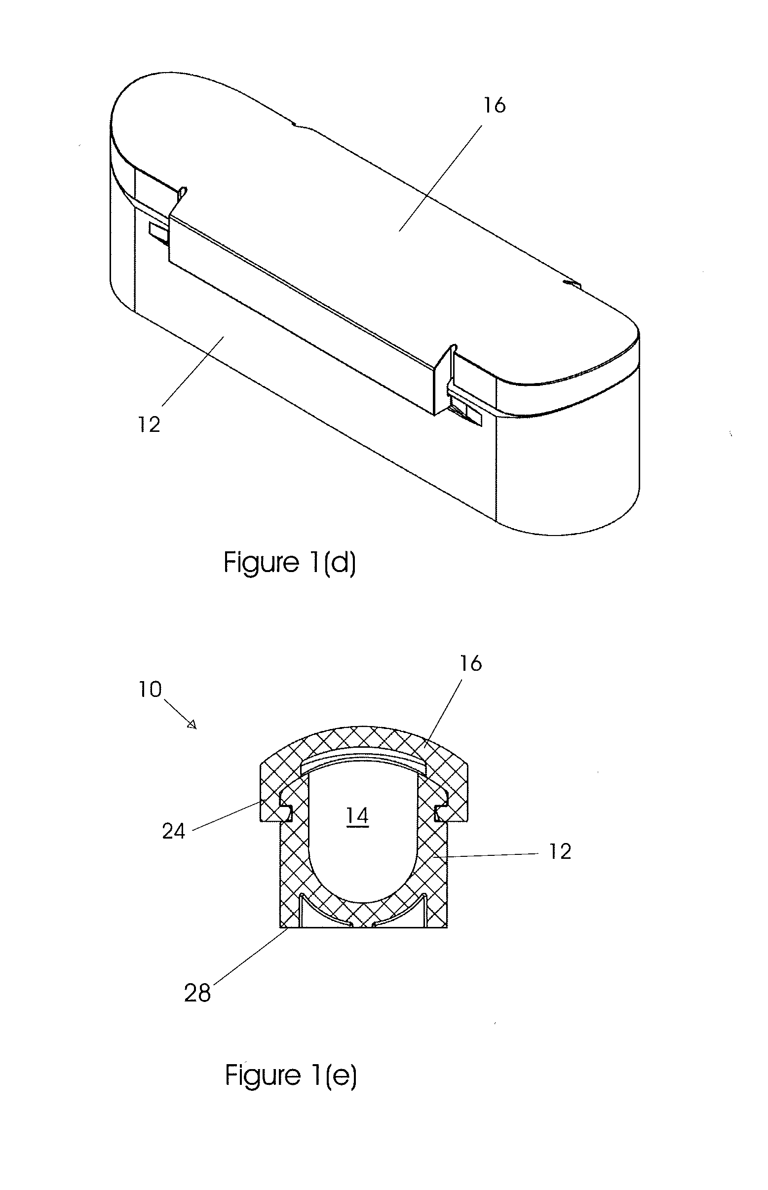
Sampling pod system and method

Active Publication Date: 2016-12-15
SAMPLING SYST
View PDF33 Cites 0 Cited by
  • Summary
  • Abstract
  • Description
  • Claims
  • Application Information

AI Technical Summary

Benefits of technology

[0004]The present invention aims to provide an improved apparatus and method of sampling granular (and the like) solids and also liquids; especially viscous liquids. A further aim/objective is to provide an apparatus and a method that allow safer, and simpler/faster transport of samples to a location for analysis than known systems; and a

Problems solved by technology

Sometimes materials being sampled are potentially hazardous to human beings or to the environment.
Such transfer (from the sampling thief) can be time consuming, especially when stringent safety precautions need to be taken.
Also, sometimes during such transfer the sample can become contaminated, or can c

Method used


Image

  • Sampling pod system and method
  • Sampling pod system and method
  • Sampling pod system and method

Examples


Example

[0029]FIGS. 4(a) to 4(f) diagrammatically illustrate a fourth embodiment of the invention. This embodiment has three sample collecting cavities (14a, 14b, 14c) located in spaced-arrangement (lengthwise) on the top face of the main body portion (12). Each of these cavities (14) are shallower than the cavities illustrated in earlier embodiments.

Example

[0030]FIG. 5 shows a fifth embodiment of the invention, the sampling pod (10) again having three sample collecting cavities (14a, 14b and 14c), but separated by a greater distance than the sampling pod illustrated in FIGS. 4(a) to 4(f). This greater separation facilitates removal of the sampled material (just prior to analysis) as the lid portion (16) is progressively slid open, as described below (see FIG. 6).

[0031]FIG. 6 shows the sampling pod (10) of FIG. 5 with the lid portion (16) in four different positions: FIGS. 6(a) and 6(b) show the lid sealing all three cavities (as it would during transfer to the location of analysis); FIGS. 6(c) and 6(d) with the lid portion (16) one third open (to allow the removal of the sampled material from first sample collecting cavity 14a; FIGS. 6(e) and 6(f) with the lid portion (16) two thirds open, to allow the (subsequent) removal of the sampled material from the second collecting cavity 14b; and FIGS. 6(f) and 6(g) show the sampling pod (10)...


PUM


Abstract

A method of, and apparatus for sampling a solid or liquid sample using a sampling tool which has a sampling rod/tube that is configured to house a sampling pod, the apparatus comprising: a main body portion with at least one sample collecting cavity; and a removable/opening lid portion that in use fits/closes over at least part of said main body portion and thereby covers and the cavity; the method further comprising the following steps: Inserting said sampling pod main body portion within said sampling rod/tube and taking a solid or liquid sample from a vessel/container; removing sampling rod/tube from said vessel or container and covering said collecting cavity to seal said cavity; transporting said sample within said sampling pod to place of a analysis; and at place of analysis removing at least part of said covering from main body portion to expose sample for analysis.

Description

TECHNICAL FIELD[0001]The present invention concerns a sampling pod system and method of use; in particular for sampling solids; semi-solids, creams; and all forms of liquids, using a type of sampling tool commonly known as a “sampling thief”.BACKGROUND ART[0002]Sampling tools such as “sampling thieves” are commonly used to sample granular materials and the like, and also liquids such as oils. Sometimes materials being sampled are potentially hazardous to human beings or to the environment. Typically, following sampling of a solid or liquid, the sample is transferred (usually manually) to a sample container, in which it is kept during transfer / transport to the location where it is analysed. Such transfer (from the sampling thief) can be time consuming, especially when stringent safety precautions need to be taken. Also, sometimes during such transfer the sample can become contaminated, or can contaminate the environment. Such transfer can also result in changes in the average sample ...

Claims


Application Information

Patent Timeline
IPC IPC(8): G01N1/04G01N1/10
CPCG01N1/10G01N1/04G01N1/08G01N1/16G01N1/18G01N2001/2071G01N1/02G01N2001/1006
Inventor FENNER, SIMON JONATHANFENNER, JONATHAN PAULFENNER, MICHAEL JOHN
Owner SAMPLING SYST
Learn More