

Liquid nitrogen enabler
- Summary
- Abstract
- Description
- Claims
- Application Information
AI Technical Summary
Benefits of technology
Problems solved by technology
Method used
Image


Examples
first embodiment
[0033] 1. the Present Invention
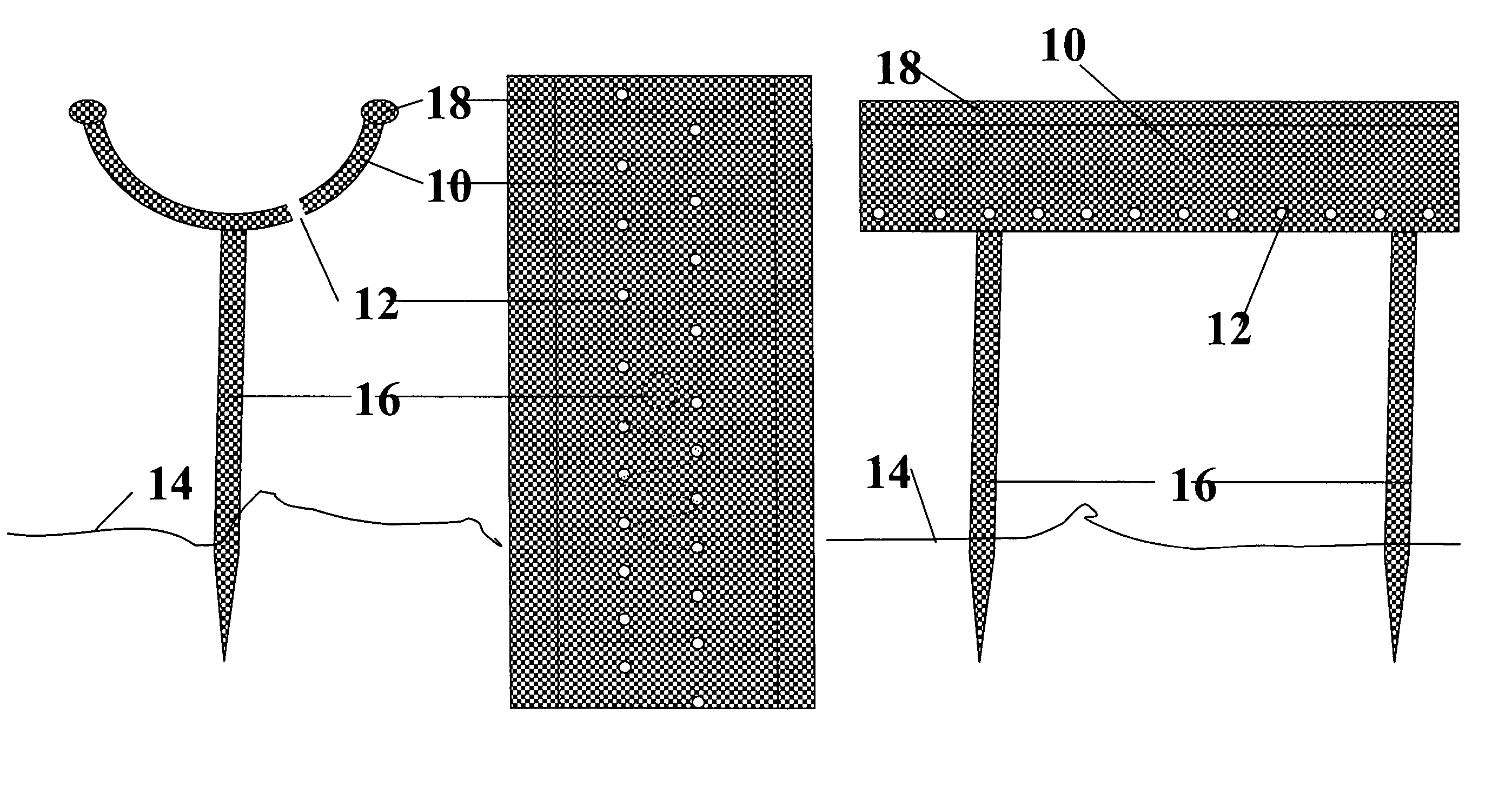
[0034] Turning now to the drawings and initially to FIGS. 1-3, a method of applying liquid nitrogen to a region using a galvanized material forming a circle around the fire region is shown. A gutter or trough 10 having a plurality of holes or apertures 12 thereon is provided. The holes 12 are provided so that upon introduction of the liquid nitrogen into the trough 10, the liquid nitrogen flows to fill the trough 10 and leaks out of the holes 12 under the force of gravity, thus generating an area of “raining” liquid nitrogen on the surface below. The application of liquid nitrogen in this manner will generate a substantially gaseous application of nitrogen, thus resulting in a substantial volume of inert nitrogen gas cooling the air and the surrounding surfaces.
[0035] Turning now to FIGS. 1a-c, an exemplary illustration of a trough design is shown. The trough comprises a plurality of spikes 16 on the underside of the trough 10 that are used to punctur...
second embodiment
[0044] 2. the Present Invention
[0045] Referring now to FIGS. 7-10, and in particular, FIGS. 7a-d, an explosion ordnance clearing device 46 is illustrated wherein a trough 10 having a plurality of apertures or holes 12 therein, such that flowing liquid nitrogen pours through the apertures 12. The trough 10 is placed over an explosive ordnance 40, otherwise known as a mine, such that the poured liquid nitrogen is applied to the mine after dripping through the apertures 12 in the trough 10. The application of the liquid nitrogen to the mine 40 substantially cools the mine so as to render the explosive material contained therein inert for a period of time long enough to safely transport the mine 40 to a nearby detonation chamber. In another embodiment of the present invention, double-sectioned legs 42 having a structural support section 44 are provided on the outside of the clearing device 46. Additionally, an inflatable inner section 48 is provided on the inside of the device 46.
[0046...
third embodiment
[0049] 3. the Present Invention
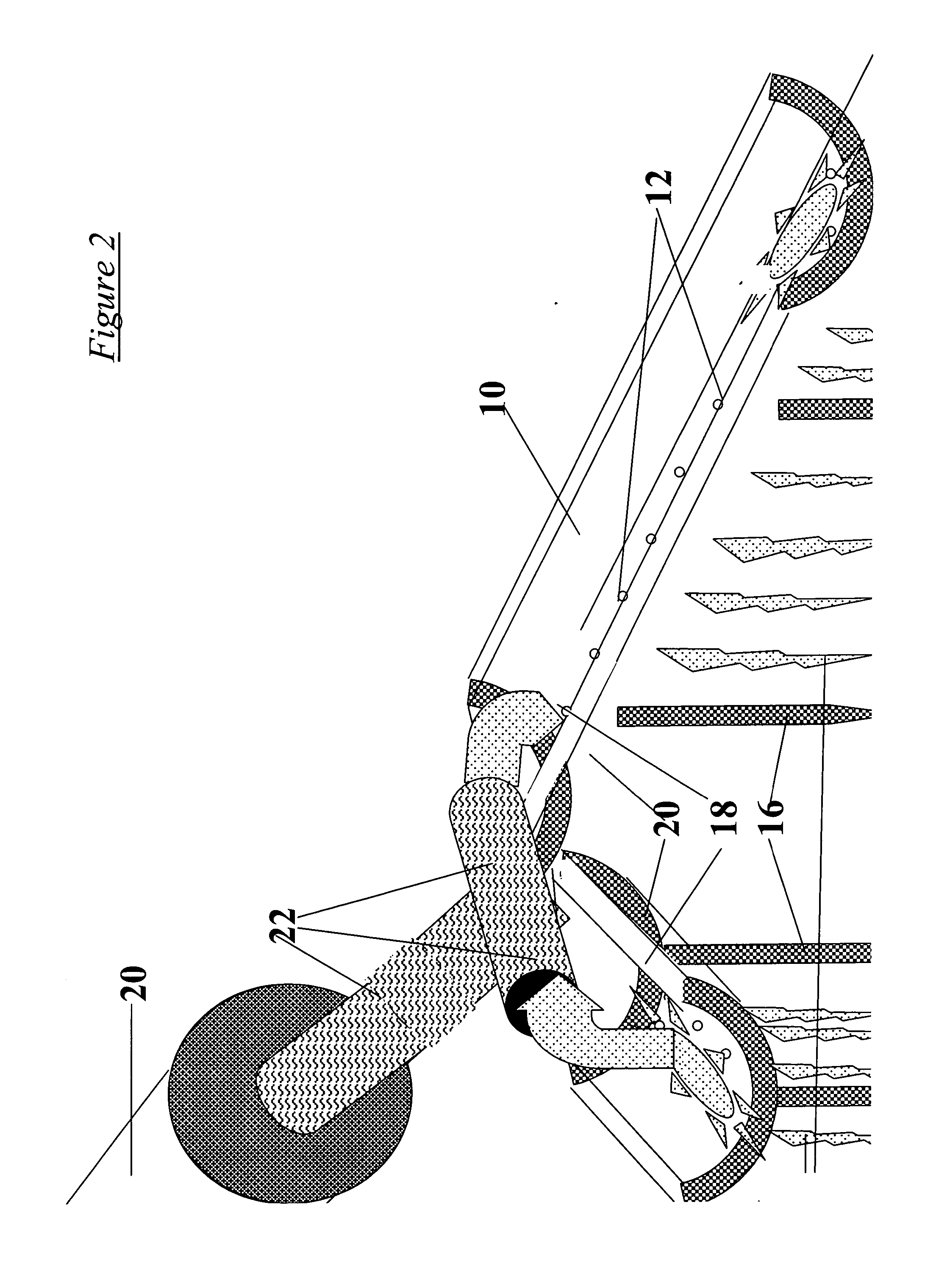
[0050] Turning now to FIG. 11, a third embodiment of the present invention is illustrated wherein liquid nitrogen is used to freeze detonators for safe removal thereof. A dewar 20 having an outlet 22 formed inside a drill bit sufficiently long enough to effectively probe near the detonator, is used to release the liquid nitrogen at the level of the detonator in order to freeze it and cool the surrounding area in the immediate vicinity to near-liquid nitrogen temperatures. This will freeze any material in a pipe or containment adjacent to the explosives as well making it safer to work. Next, while retaining the explosives at near-liquid nitrogen temperature, the surrounding area is dug out and removed. As shown in FIG. 11, if the explosive is tied to a well pipe 50, a water cutter 52, or similar instrument, may be employed in parallel to cut the explosive loose of the pipe 50. Liquid nitrogen cooling should continue through removing the explosives and l...
PUM
 Abstract
Description
Claims
Application Information