
Fluid receiver

Active Publication Date: 2011-09-22
TOBECK TRUSTEE OF PROGRESSIVE ENDEAVOURS TRUST COLIN GILBERT +1
View PDF9 Cites 1 Cited by
  • Summary
  • Abstract
  • Description
  • Claims
  • Application Information

AI Technical Summary

Benefits of technology

[0009]The invention provides a fluid receiver in which the strength traditionally provided by a load bearing chassis is encompassed into the design of the receiver itself. Thus, the fluid receiver of the invention can be towed behind a vehicle without first being mounted to a chassis or sub-frame. Typical features of a chassis, such as axle mounts and suspension are able to be attached to the fluid receiver of the invention to form an integral receiver-chassis system. This allows the fluid receiver to be lower to the ground, resulting in the overall height of the fluid receiver to be lower with respect to the ground and resulting in a lower centre of gravity. The lower centre of gravity increases the static rollover threshold of a vehicle carrying or towing the receiver, thereby increasing stability and providing for the safer transportation and confinement of fluid, especially over uneven terrain or when turning corners.

Problems solved by technology

Traditional problems associated with the transportation of fluid relate to poor stability of the fluid receivers as they travel over uneven surfaces, traverse sloped planes, or confront an incline or decline.
These problems arise due to a high centre of gravity resulting from the use of a chassis or sub-frame.
Another problem with known fluid receivers is the freely moving fluid within fluid receivers whilst in transit, causing the load to become unstable.
As the fluid receiver changes direction, gradient, tilt, or speed, the fluid mass maintains its original forces, resulting in movement of the fluid mass within the receiver, which causes the load to become unstable whilst the mass corrects itself to the new forces generated by changes in movement of the fluid receiver.
The reduced stability resulting from the contained fluid mass moving during transit is compounded by the elevated centre of gravity because of the use of a chassis or sub-frame, making the vehicle more susceptible to rolling over.
Therefore, the transportation of fluid is often a dangerous and difficult job, especially in “off-road” applications where the uneven road surface creates almost constant movement of the fluid mass at an elevated centre of gravity within the receiver, resulting in a low static rollover threshold and a highly unstable load.
As a result, another problem with known fluid receivers is that the payload capacity of the prime mover, or towed carrier, is reduced.

Method used


Image

  • Fluid receiver
  • Fluid receiver
  • Fluid receiver

Examples


Embodiment Construction

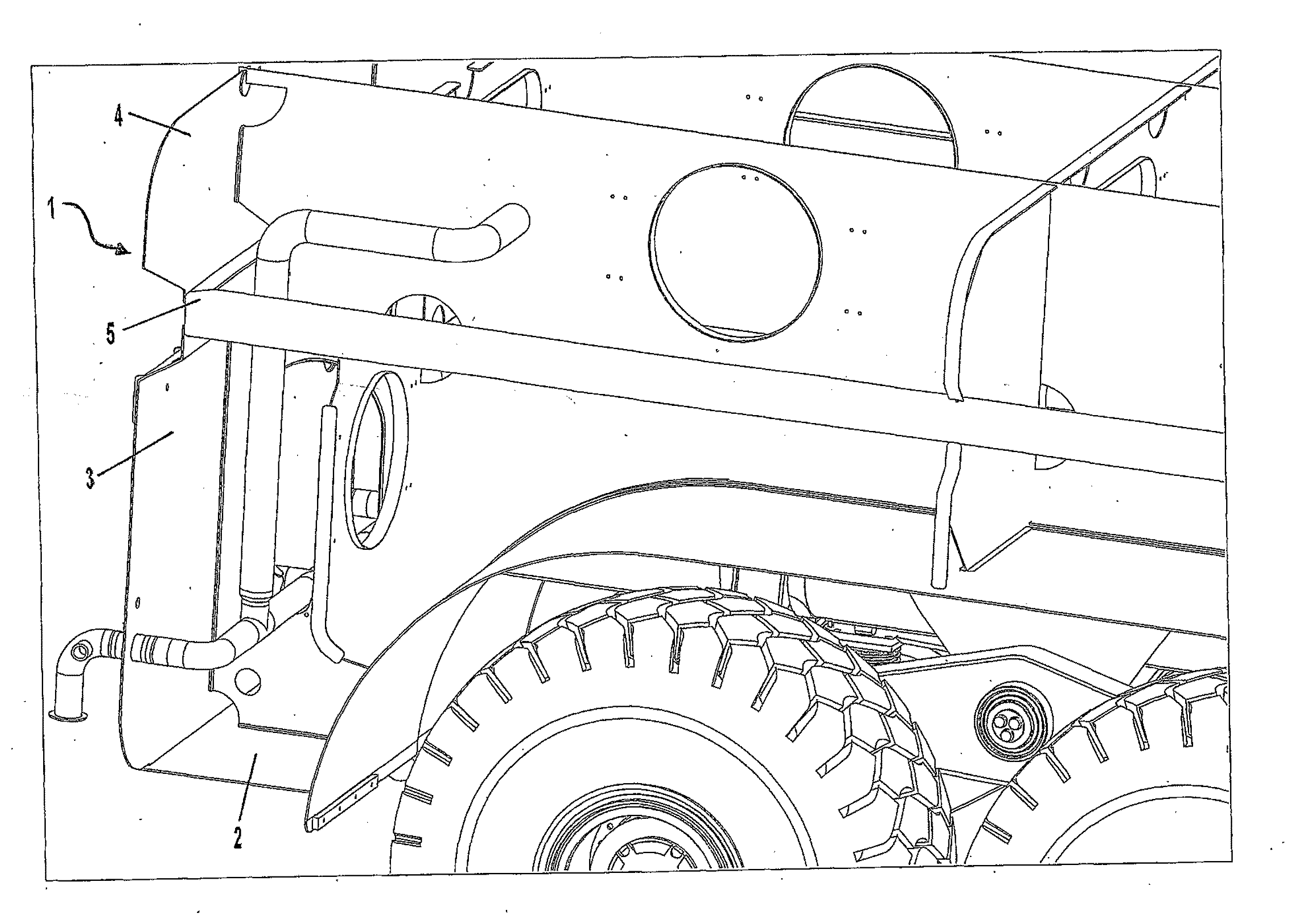
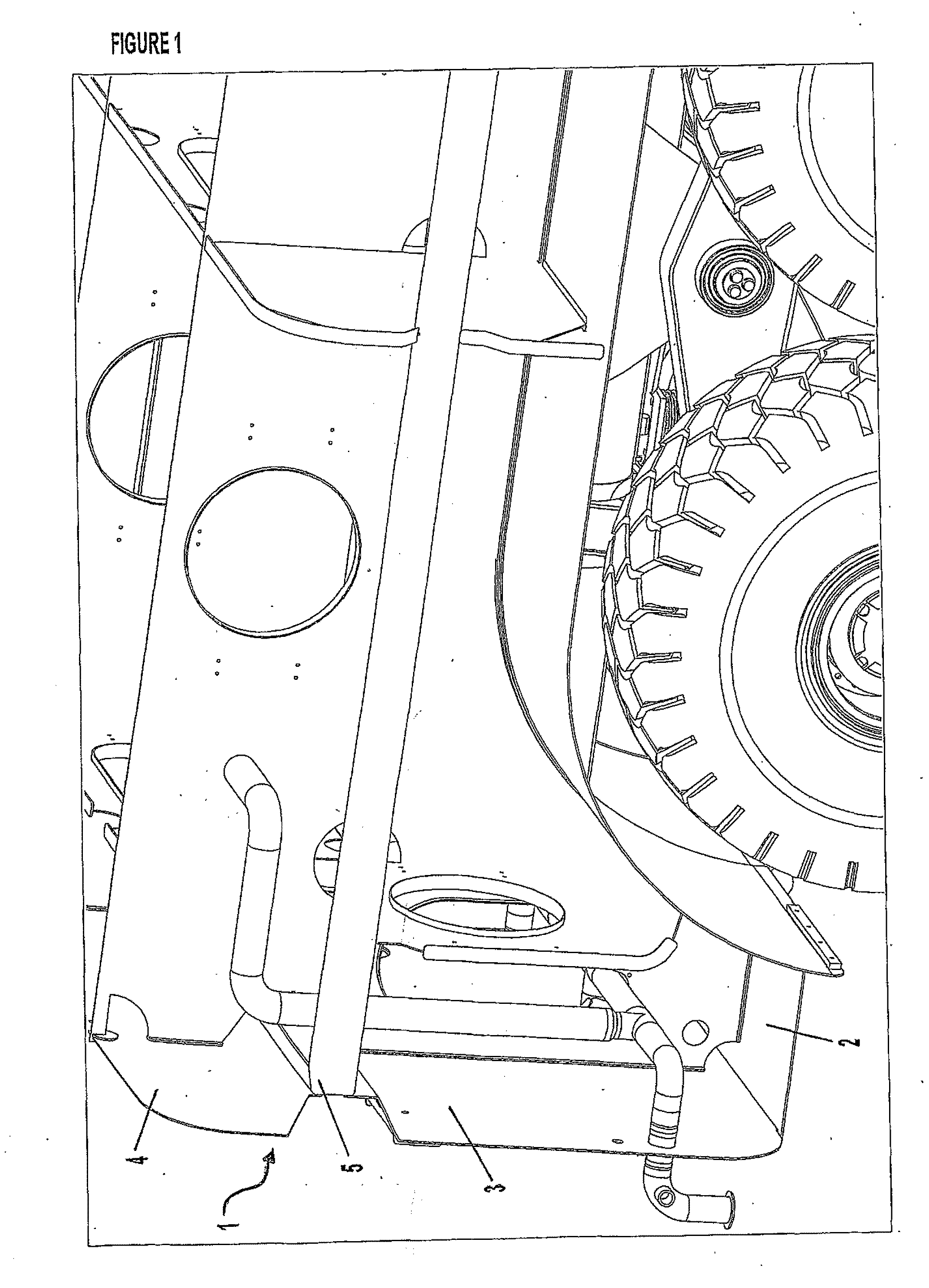
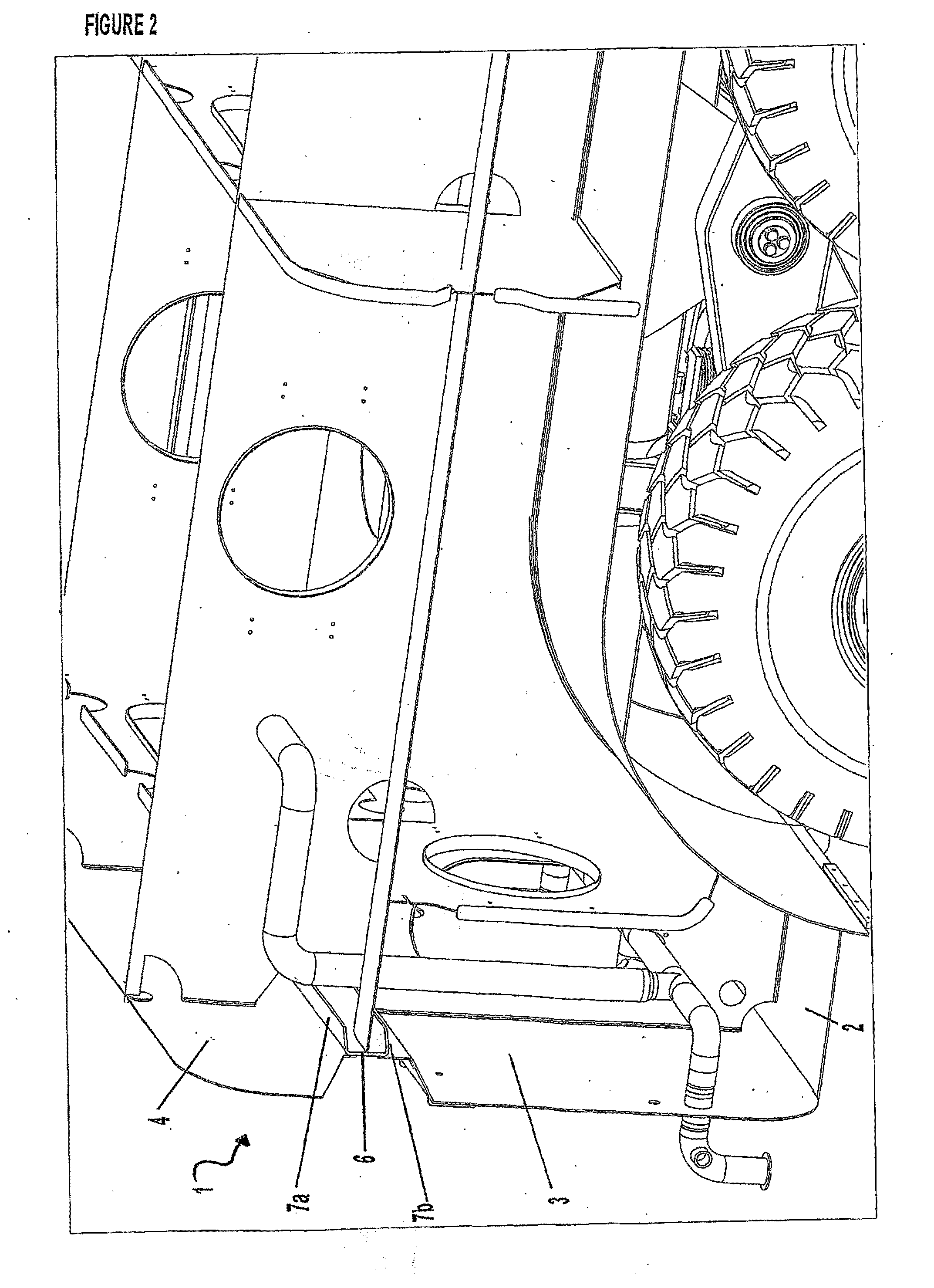
[0034]In one form, the fluid receiver of the invention comprises a receiver body 1 comprising a floor 2, side sections 3 and, optionally, a top section 4. In the embodiment shown in FIGS. 1 and 2, the receiver side sections 3 are welded to a top section 4 along a frame 5 that substantially surrounds the upper portion of the receiver. The frame 5 may comprise a base 6 and a pair of arms 7a, 7b that extend from each side of the base to form a substantially U-shaped section or channel. The base 6 of the frame, or bottom of the “U” shape, is positioned to face toward the side walls 3 of the receiver body.

[0035]The shape of the side sections 3 and top section 4 and the joint created by the weld between these sections and the frame 5 provide strength to the receiver and allow for lighter material (such as mild steel) to be used in the side sections and top section. The shape of each wall includes an angle sloped toward the frame 5. This shape of the angled side sections and top section is...


PUM


Abstract

The invention relates to a fluid receiver for attaching to a vehicle. The fluid receiver comprises a receiver body having side walls extending upwardly from a receiver floor. A wheel arch is formed within the receiver floor and comprises a reinforced mounting plate to which is attached a mounting system for attaching wheels to the fluid receiver. The receiver is, therefore, adapted to be attached directly to a wheel mounting system and suspension system without needing to be mounted to a chassis or sub-frame. As such, the receiver has a lower centre of gravity and higher static rollover threshold, resulting in increased stability, particularly when the receiver is attached to a vehicle negotiating rough terrain or slopes.

Description

FIELD OF THE INVENTION[0001]This invention relates to a transportable fluid receiver that is integral with the load bearing structure of a vehicle (prime mover) or carrier for towing behind a vehicle.BACKGROUND OF THE INVENTION[0002]Fluid receivers confine and store fluid and can be used to transport fluid.[0003]Fluid receivers that confine, store, and act as a means for fluid transportation are traditionally constructed using a “tank type” vessel mounted on a chassis or sub-frame. This is particularly the case when the receiver has its own set of drive axle(s) and wheels and is towed behind a vehicle / prime mover.[0004]Traditional problems associated with the transportation of fluid relate to poor stability of the fluid receivers as they travel over uneven surfaces, traverse sloped planes, or confront an incline or decline. These problems arise due to a high centre of gravity resulting from the use of a chassis or sub-frame. Traditionally, the entire fluid receiver is mounted above ...

Claims


Application Information

Patent Timeline
IPC IPC(8): B65D88/12
CPCB60G5/02B60G2200/341B60P3/2225B60G2204/143B60G2202/143B60P3/243
Inventor VANAGOSOOM, EKAPOTE
Owner TOBECK TRUSTEE OF PROGRESSIVE ENDEAVOURS TRUST COLIN GILBERT
Learn More