
Apparatus and method for inhibiting roundoff error in a floating point argument reduction operation

a floating point argument and reduction operation technology, applied in the direction of digital data processing details, instruments, electric digital data processing, etc., can solve the problems of large and irregular lookup tables, significant increases in circuitry cost and complexity,

Active Publication Date: 2016-12-15
ARM LTD
View PDF2 Cites 6 Cited by
  • Summary
  • Abstract
  • Description
  • Claims
  • Application Information

AI Technical Summary

Benefits of technology

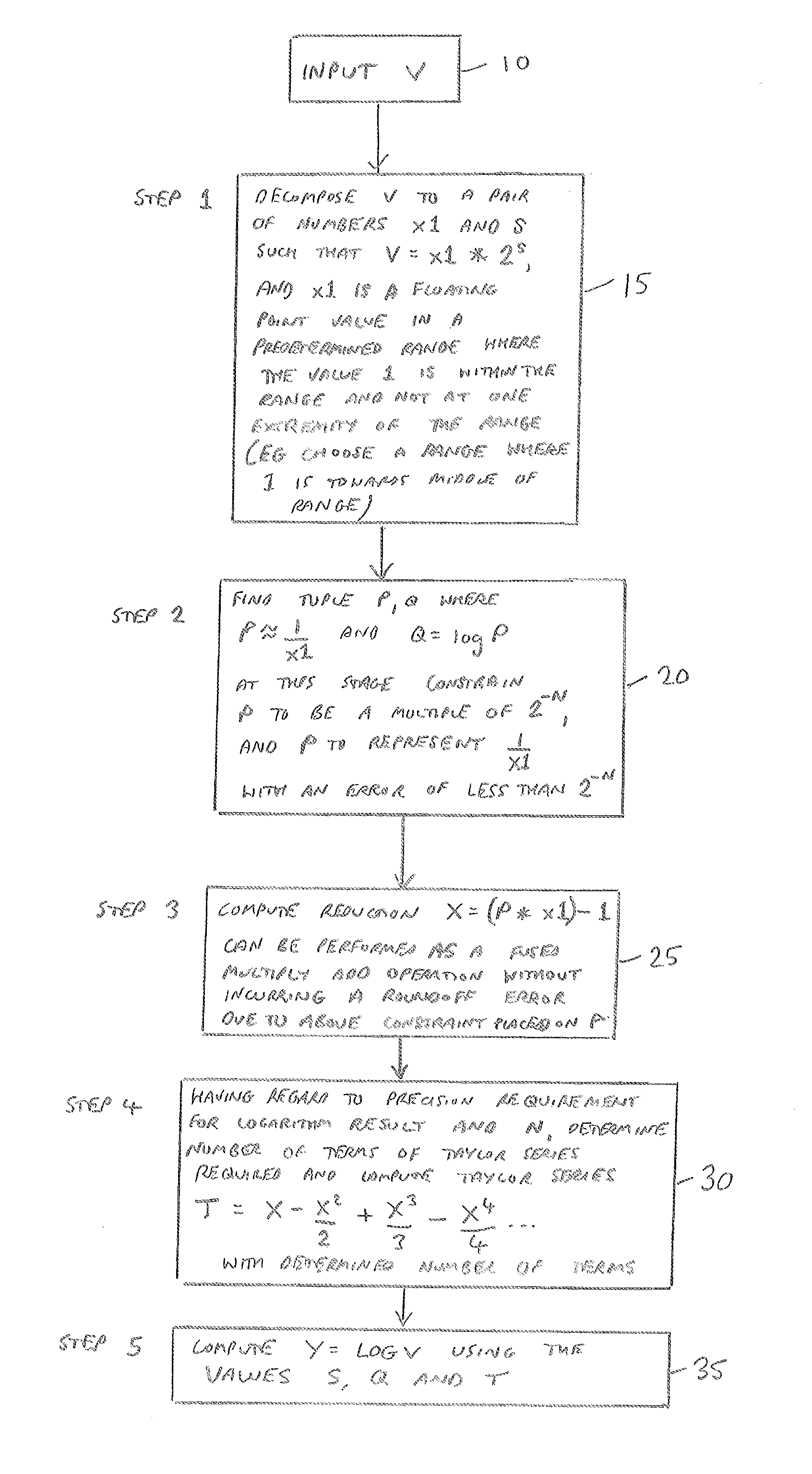
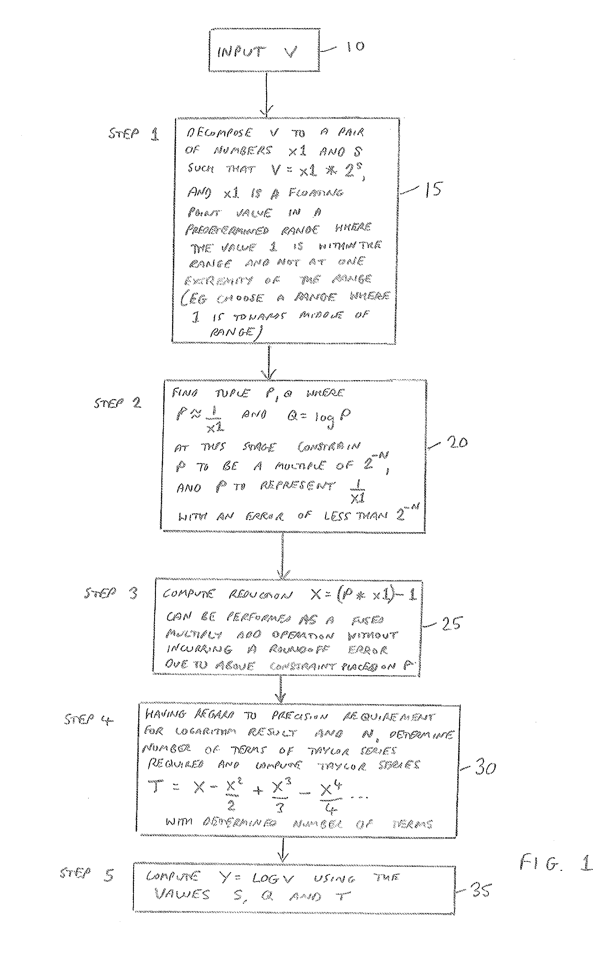
The patent describes a method and apparatus for reducing roundoff error in a floating point argument reduction operation. The method involves determining an estimated reciprocal of a first floating point value and constraining its magnitude and error bound in dependence on a specified value N. This constraint helps to inhibit roundoff error in a third floating point value that is generated by an argument reduction operation using the first and second floating point values as inputs. The technical effect of this invention is to improve the accuracy and reliability of floating point operations.

Problems solved by technology

However, known techniques for performing an argument reduction step without introducing roundoff error rely heavily on multi-precision arithmetic, which significantly increases the cost and complexity of the circuitry.
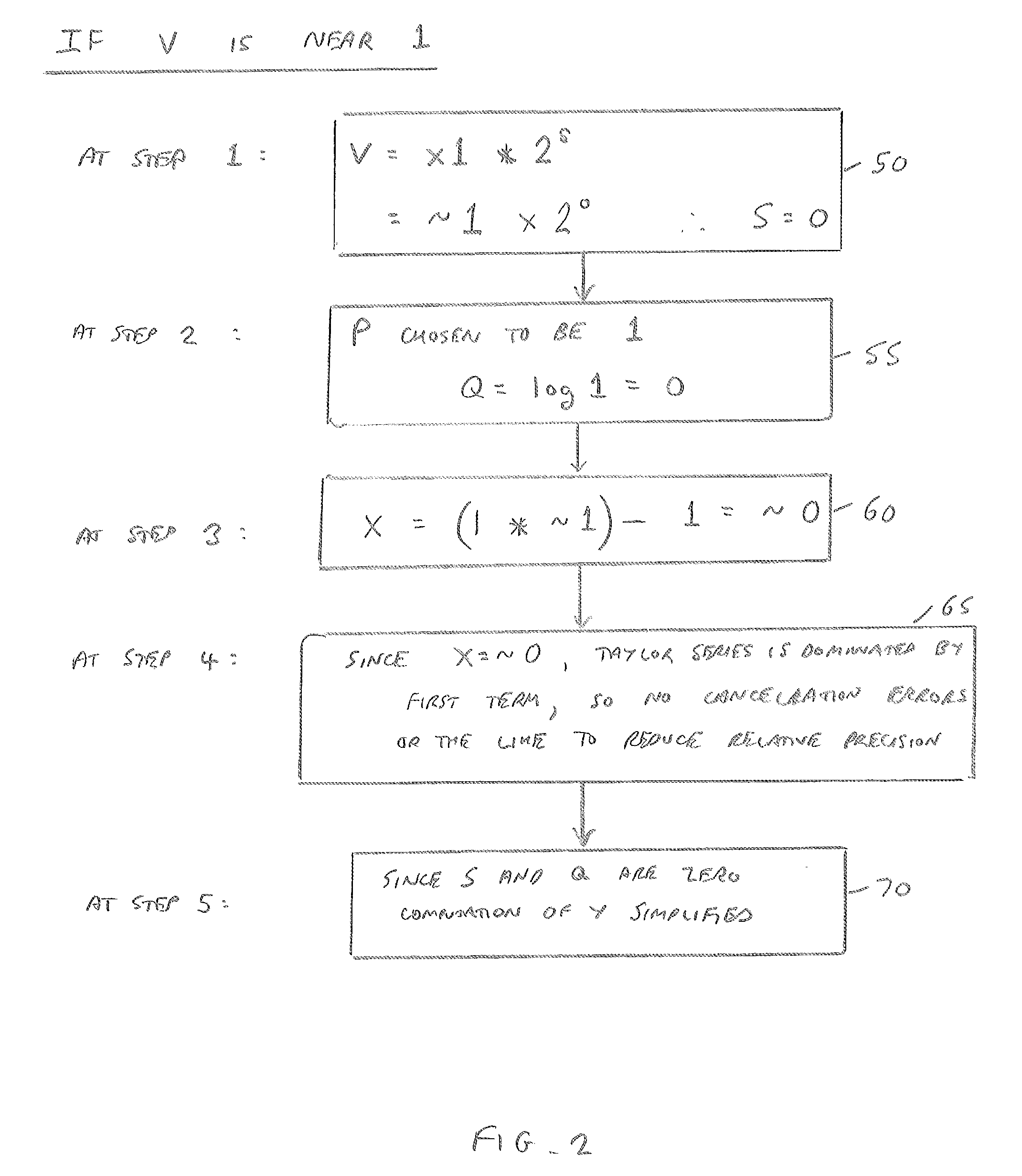
However, such an approach can result in the need for a very large and irregular lookup table to provide sufficiently-accurate piecewise-cubic functions for input values close to 1.

Method used


Image

  • Apparatus and method for inhibiting roundoff error in a floating point argument reduction operation
  • Apparatus and method for inhibiting roundoff error in a floating point argument reduction operation
  • Apparatus and method for inhibiting roundoff error in a floating point argument reduction operation

Examples


Embodiment Construction

[0018]Before discussing the embodiments with reference to the accompanying figures, the following description of embodiments is provided.

[0019]In accordance with one embodiment an apparatus is provided that comprises reciprocal estimation circuitry to determine a second floating point value that is an estimated reciprocal of an input first floating point value. In accordance with the described embodiment, the second floating point value has both its magnitude and its error bound constrained in dependence on a specified value N. Argument reduction circuitry then performs an argument reduction operation using the first and second floating point values as inputs, in order to generate a third floating point value. In accordance with the described embodiment, the use of the specified value N to constrain both the magnitude and the error bound of the second floating point value causes roundoff error to be inhibited in the third floating point value that is generated by the argument reduct...


PUM


Abstract

An apparatus and method are provided for inhibiting roundoff error in a floating point argument reduction operation. The apparatus has reciprocal estimation circuitry that is responsive to a first floating point value to determine a second floating point value that is an estimated reciprocal of the first floating point value. During this determination, the second floating point value has both its magnitude and its error bound constrained in dependence on a specified value N. Argument reduction circuitry then performs an argument reduction operation using the first and second floating point values as inputs, in order to generate a third floating point value. The use of the specified value N to constrain both the magnitude and the error bound of the second floating point value causes roundoff error to be inhibited in the third floating point value that is generated by the argument reduction operation. This enables such an argument reduction operation to be used as part of a more complex computation, such as a logarithm computation, with the inhibiting of roundoff error in the argument reduction result allowing the overall result to exhibit small relative error across the whole representable input range.

Description

BACKGROUND[0001]The present technique relates to an apparatus and method for inhibiting roundoff error in a floating point argument reduction operation.[0002]There are a number of floating point computations used in modern data processing systems that require specified degrees of accuracy in the results obtained when performing those computations. One example is a floating point logarithm computation. For example in the field of graphics processing units (GPUs), there are several application programming interfaces that typical GPU designs must support, where logarithm functions are required. These functions are typically base-2 and base-e (natural) logarithms, that may for example take a single precision (FP32) floating point input value, and produce a single precision floating point result. It is often the case that these logarithm functions are required to exhibit small relative error for the whole representable input range.[0003]One known approach for implementing a logarithm fun...

Claims


Application Information

Patent Timeline
Patent Type & Authority Applications(United States)
IPC IPC(8): G06F7/499G06F7/483
CPCG06F7/483G06F7/49915
Inventor NYSTAD, JORN
Owner ARM LTD
Learn More