Sensor calibration systems and methods

a technology of calibration system and sensor, applied in the field of systems, apparatus and methods for improving calibration systems, can solve the problems of high cost of cabling and installation, time-consuming and difficult, and inability to access ambient readings otherwise difficult,

Active Publication Date: 2016-12-22
TRANE INT INC
View PDF8 Cites 23 Cited by
  • Summary
  • Abstract
  • Description
  • Claims
  • Application Information

AI Technical Summary

Benefits of technology

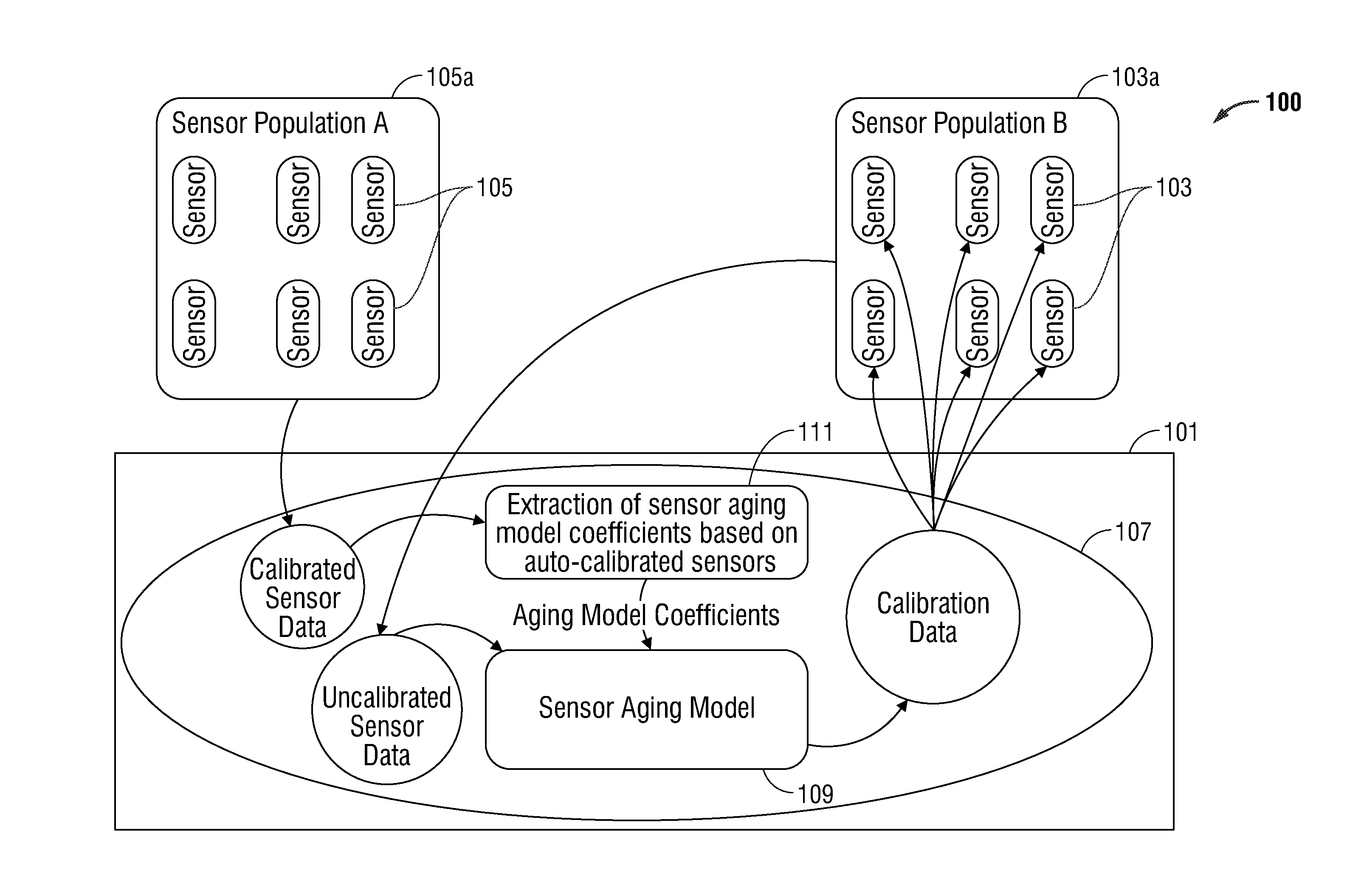
This patent describes a system for calibrating sensors in a computer server. The system receives calibrated sensor data from calibrated sensors and outputs calibration data to uncalibrated sensors. The calibration module includes an aging model that receives the calibration data and inputs it into the model to create calibration data for the uncalibrated sensors. The calibration data can be unique to each sensor based on its local conditions. The system can also receive uncalibrated sensor data and input it into the aging model to output the calibration data. The technical effect of this patent is to provide a system for calibrating sensors that can automatically calibrate sensors based on their local conditions and provide accurate calibration data.

Problems solved by technology

Hard-wired systems are generally reliable, but the costs of cabling and installation are high.
However, in buildings that are constantly occupied, or in places where access to an ambient reading is otherwise difficult, traditional CO2 sensors must be manually recalibrated (e.g., by removal and / or supplying the sensor with a suitable calibration gas).
This may be time consuming and difficult, especially where sensor devices are located in hard to reach locations.

Method used


Image

  • Sensor calibration systems and methods
  • Sensor calibration systems and methods
  • Sensor calibration systems and methods

Examples


Embodiment Construction

[0032]Particular illustrative embodiments of the present disclosure are described hereinbelow with reference to the accompanying drawings; however, the disclosed embodiments are merely examples of the disclosure, which may be embodied in various forms. Well-known functions or constructions and repetitive matter are not described in detail to avoid obscuring the present disclosure in unnecessary or redundant detail. Therefore, specific structural and functional details disclosed herein are not to be interpreted as limiting, but merely as a basis for the claims and as a representative basis for teaching one skilled in the art to variously employ the present disclosure in virtually any appropriately detailed structure. In this description, as well as in the drawings, like-referenced numbers represent elements which may perform the same, similar, or equivalent functions. The word “exemplary” is used herein to mean “serving as an example, instance, or illustration.” Any embodiment descri...


PUM


Abstract

A system for calibrating sensors includes at least one computer server configured to be in communication with at least one uncalibrated sensor and at least one calibrated sensor, and a calibration module stored on the server. The calibration module may be configured to receive calibrated sensor data from the at least one calibrated sensor, and output calibration data to the at least one uncalibrated sensor.

Description

CROSS-REFERENCE TO RELATED APPLICATION[0001]This application claims the benefit of and priority to U.S. Provisional Application Ser. No. 62 / 180,653 entitled “SENSOR CALIBRATION SYSTEMS AND METHODS” and filed Jun. 17, 2015, the entirety of which is hereby incorporated by reference herein for all purposes.BACKGROUND[0002]1. Technical Field[0003]The present disclosure is directed to systems, apparatus, and methods for improving calibration systems, more particularly, calibration systems for CO2 sensors used in HVAC installations.[0004]2. Background of Related Art[0005]Heating, ventilation, and air conditioning systems (HVAC systems) typically utilize one or more sensors, thermostats, and / or HVAC controllers to monitor environmental conditions in a building and to operate HVAC equipment installed at the building. Traditional systems utilize components which are interconnected using traditional hard-wiring techniques using electrical conductors routed within the physical structure. Hard-...

Claims


Application Information

Patent Timeline
IPC IPC(8): G01N33/00
CPCG01N33/0008G01D18/002
Inventor VAN TOL, JOSHUA
Owner TRANE INT INC
Why Eureka
Try Eureka