
Systems, Methods, and Apparatuses for Downhole Lateral Detection Using Electromagnetic Sensors

a technology of electromagnetic sensors and electromagnetic sensors, applied in the field of downhole tools, can solve the problems of high cost, high accuracy of methods, and high cost of kickover and wand techniques, and achieve the effects of low cost, high accuracy, and low cos

Active Publication Date: 2016-12-22
SAUDI ARABIAN OIL CO
View PDF0 Cites 4 Cited by
  • Summary
  • Abstract
  • Description
  • Claims
  • Application Information

AI Technical Summary

Benefits of technology

The patent text discusses the problems with current methods of detecting laterals in wells and proposes a new system that can be used at all stages of well development. The new system uses a subsurface unit with a ruggedized encapsulation that can be introduced into a motherbore through a surface entry and has an uphole end and downhole end relative to the motherbore surface entry. The subsurface unit includes a control and communication subsystem that can control and modulate a wideband electromagnetic signal to detect laterals. The system also includes one or more wideband antennas that can be responsive to the duplexer and transmitter and detect reflections of the electromagnetic pulse. The surface unit can include one or more processors and displays for data transfer and analysis. The technical effects of this patent text are improved and cost-effective detection of laterals in wells, with the ability to use the system at all stages of well development.

Problems solved by technology

Applicant has recognized a number of problems in current approaches to detect laterals.
First, this technique is prone to error as an operator can fail to locate a lateral simply because an inappropriate wand length was chosen.
In addition, Applicant has recognized that these downhole contraptions do not include means for accurate downhole depth control and yet rely heavily on such depth control to detect laterals.
Hence, Applicant has recognized that this method can be highly inaccurate.
In addition, the kickover and wand technique is expensive, and the added cost provides little in the way of added benefit.
If primary casing has been installed, but is not yet cemented in place, these fixtures cannot be installed.
Moreover, there can be situations in which the primary casing has not been installed at all.
Hence, this technique can be used only at certain stages of development, and then only at great cost.

Method used


Image

  • Systems, Methods, and Apparatuses for Downhole Lateral Detection Using Electromagnetic Sensors
  • Systems, Methods, and Apparatuses for Downhole Lateral Detection Using Electromagnetic Sensors
  • Systems, Methods, and Apparatuses for Downhole Lateral Detection Using Electromagnetic Sensors

Examples


Embodiment Construction

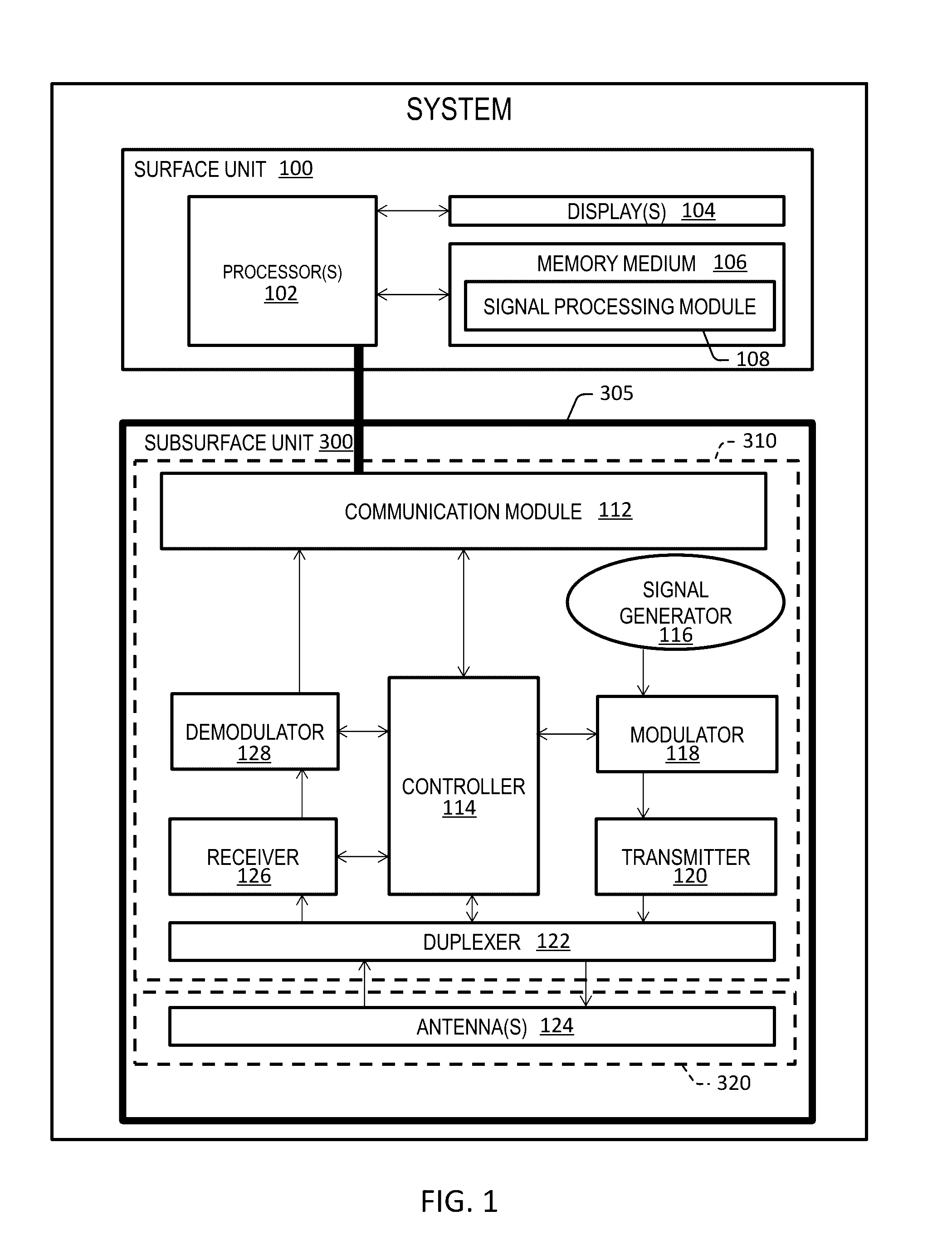
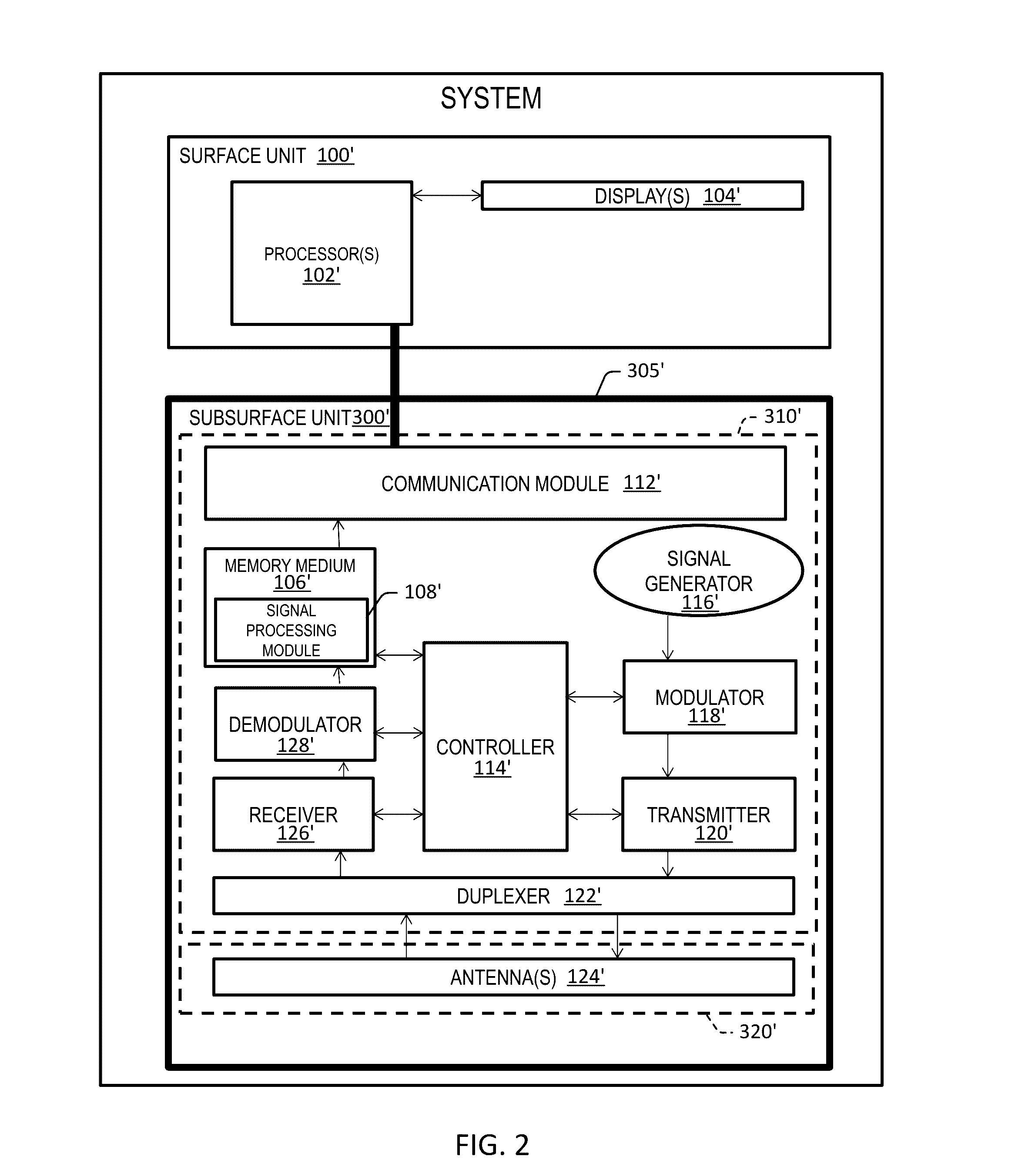
[0031]So that the manner in which the features and advantages of the embodiments of systems, methods, and apparatuses of the present invention, as well as others, which will become apparent, may be understood in more detail, a more particular description of the embodiments briefly summarized in the preceding section may be had by reference to the embodiments thereof, which are illustrated in the appended drawings, which form a part of this specification. It is to be noted, however, that the drawings illustrate only various embodiments of the embodiments and, therefore, are not to be considered limiting of the embodiments of the present invention's scope as the invention includes other effective embodiments as well.

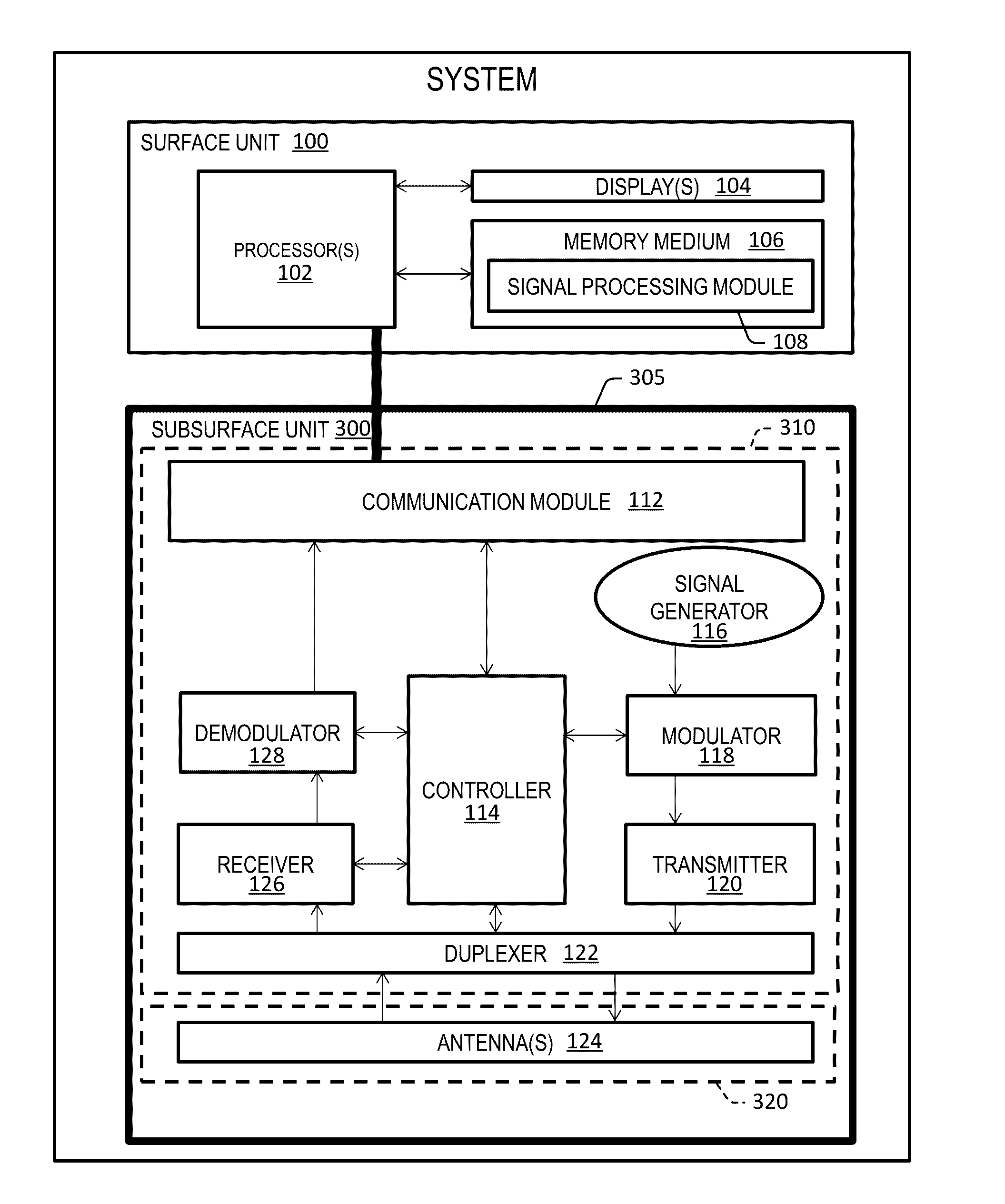
[0032]FIGS. 1 and 2 depict system embodiments. To provide a clearer disclosure, these figures are discussed together for the most part, with differences being highlighted. System embodiments can include a subsurface unit 300, 300′, a surface unit 100, 100′, and a wireline ...


PUM


Abstract

Disclosed are systems, methods, and apparatuses to detect one or more downhole laterals in a wellbore using electromagnetic sensors. Certain embodiments include a subsurface unit including a ruggedized encapsulation resistant to heat, pressure, and variations in pH. The systems and apparatuses are communicable with surface controls.

Description

RELATED APPLICATIONS[0001]This application claims the benefit of U.S. Provisional Patent Application No. 62 / 183,004 filed on Jun. 22, 2015 and titled “SYSTEMS, METHODS, AND APPARATUSES FOR DOWNHOLE LATERAL DETECTION USING ELECTROMAGNETIC SENSORS”, which is hereby incorporated by reference in its entirety.FIELD OF INVENTION[0002]Embodiments relate to oil and gas exploration and, more particularly, to downhole tools.BACKGROUND OF THE INVENTION[0003]In recent years, it has become possible to drill and maintain increasingly complicated wellbores. In some cases, rather than drilling multiple vertical wells, it may be advantageous to drill relatively fewer vertical wells, but branch out from these vertical wells with a greater number of lateral wells. Hence, a primary wellbore with laterals branching out from it can provide the coverage desired of a downhole formation at less expense and time than would be needed to achieve the same coverage with multiple vertical wells. The savings in ti...

Claims


Application Information

Patent Timeline
Patent Type & Authority Applications(United States)
IPC IPC(8): G01V3/28
CPCG01V3/28G01V3/26E21B41/0035E21B47/085E21B47/13
Inventor ARSALAN, MUHAMMADAHMAD, TALHA JAMALNOUI-MEHIDI, MOHAMED NABIL
Owner SAUDI ARABIAN OIL CO
Learn More