
Lithographic apparatus with data processing apparatus

a data processing and lithographic technology, applied in the field of lithographic equipment, can solve the problems of poor patterning performance, poor performance of the manufacturing process as a whole, and the degraded performance parameters of critical dimension (cd) and cd uniformity in particular, so as to improve the wafer level alignment performance without adversely affecting throughput

Active Publication Date: 2016-12-22
ASML NETHERLANDS BV
View PDF3 Cites 21 Cited by
  • Summary
  • Abstract
  • Description
  • Claims
  • Application Information

AI Technical Summary

Benefits of technology

The patent text aims to improve the performance of wafer level alignment without affecting the throughput of the existing lithographic apparatus. The goal is to generate high resolution wafer height maps.

Problems solved by technology

Failure to adjust the focus of the projection system may result in poor patterning performance and consequently poor performance of the manufacturing process as a whole.
Performance parameters such as critical dimension (CD) and CD uniformity in particular will be degraded by poor focus.
A known problem with optical level sensors is that different substrates, and different parts of a substrate, will interact differently with the measurement beams of radiation.
In other words, the height measurements obtained by a level sensor are subject to process-dependent effects and do not always give the true height.
However, such UV level sensors are not available in existing apparatuses, and will still only measure the height at specific sample locations.
However, the use of these sensors may be highly time consuming and they are not generally suitable for integration in the lithographic apparatus itself.
It is also noted at this point that the spatial resolution of level sensors and non-optical inspection apparatuses may be limited.
Existing sensors do not allow the height map to represent precisely the boundary between regions of very different process dependency.
For example, level sensors may not be able to measure sharp area boundaries in product topography.

Method used


Image

  • Lithographic apparatus with data processing apparatus
  • Lithographic apparatus with data processing apparatus
  • Lithographic apparatus with data processing apparatus

Examples


Embodiment Construction

[0037]Before describing embodiments of the invention in detail, it is instructive to present an example environment in which embodiments of the present invention may be implemented.

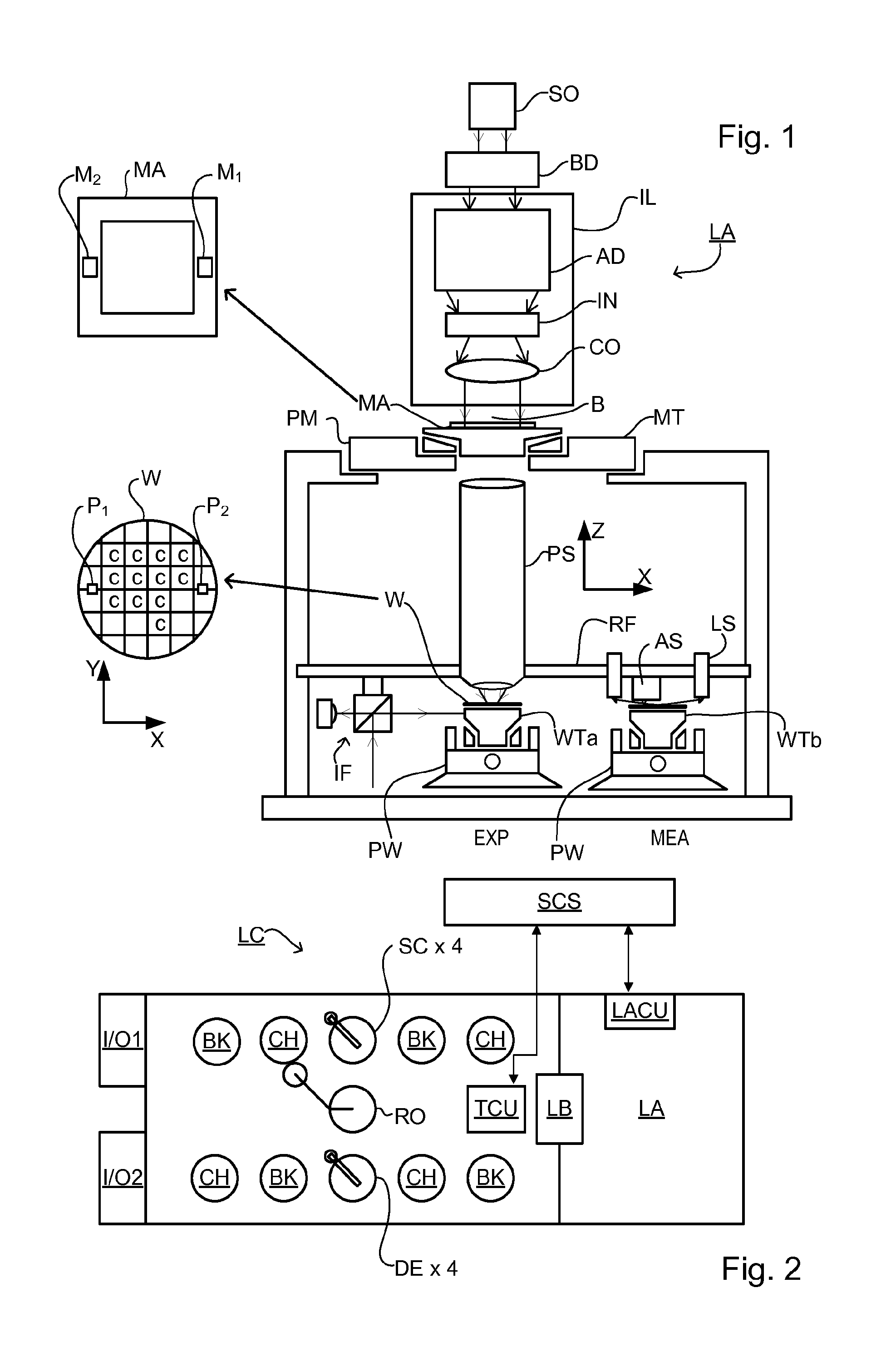
[0038]FIG. 1 schematically depicts a lithographic apparatus LA. The apparatus includes an illumination system (illuminator) IL configured to condition a radiation beam B (e.g., UV radiation or DUV radiation), a patterning device support or support structure (e.g., a mask table) MT constructed to support a patterning device (e.g., a mask) MA and connected to a first positioner PM configured to accurately position the patterning device in accordance with certain parameters; a substrate table (e.g., a wafer table) WT constructed to hold a substrate (e.g., a resist coated wafer) W and connected to a second positioner PW configured to accurately position the substrate in accordance with certain parameters; and a projection system (e.g., a refractive projection lens system) PS configured to project a pattern im...


PUM


Abstract

A lithographic apparatus applies a pattern onto a substrate using an optical projection system. The apparatus includes an optical level sensor and an associated processor for obtaining a height map of the substrate surface prior to applying the pattern. A controller uses the height map to control focusing with respect to the projection system when applying the pattern. The processor is further arranged to use information relating to processing previously applied to the substrate to define at least first and second regions of the substrate and to vary the manner in which the measurement signals are used to control the focusing, between the first and second regions. For example, an algorithm to calculate height values from optical measurement signals can be varied according to differences in known structure and / or materials. Measurements from certain regions can be selectively excluded from calculation of the height map and / or from use in the focusing.

Description

CROSS-REFERENCE TO RELATED APPLICATIONS[0001]This application is related to EP application number 14157664.5, filed Mar. 4, 2014 which is incorporated by reference herein in its entirety.BACKGROUND[0002]Field of the Invention[0003]The present disclosure relates to lithographic apparatus. The disclosure relates in particular to the measurement of local height deviations, which are important for focusing in optical lithography. The disclosure further relates to methods of manufacturing devices by lithography, and to data processing apparatuses and computer program products for implementing parts of such apparatus and methods.[0004]Background Art[0005]A lithographic apparatus is a machine that applies a desired pattern onto a substrate, usually onto a target portion of the substrate. A lithographic apparatus can be used, for example, in the manufacture of integrated circuits (ICs). In that instance, a patterning device, which is alternatively referred to as a mask or a reticle, may be ...

Claims


Application Information

Patent Timeline
IPC IPC(8): G03F7/20
CPCG03F7/70641G03F7/70725G03F9/7019G03F9/7026G03F9/7092G03F7/70275
Inventor SCHMITT-WEAVER, EMIL PETERHENKE, WOLFGANGPRENTICE, CHRISTOPHERSTAALS, FRANKTEL, WIM TJIBBO
Owner ASML NETHERLANDS BV
Learn More