Coaxial double layer parachute

a double-layer parachute and coaxial technology, applied in the field of parachute, can solve the problems of less trust in the use of parachuting decelerator, large height requirement for parachuting, and relatively complicated manual operation and skills, so as to reduce unexpected swing and increase tensile strength

Active Publication Date: 2016-12-29
LIAO SHUEH CHIH
View PDF9 Cites 1 Cited by
  • Summary
  • Abstract
  • Description
  • Claims
  • Application Information

AI Technical Summary

Benefits of technology

[0008]To achieve the above objective, a coaxial double layer parachute in accordance with the present invention comprises an inner inflatable body and an outer canopy which are located along a central axis. The inner inflatable body can be obviously lift to a certain height since the inner inflatable body is filled with helium, a less dense gas than air, to generate a first buoyance. When the payload connected to the inner inflatable body and the outer canopy falls, the ambient air flows will enter an inflation space via the annular air inlets at the lower end of the outer canopy to produce a second buoyance, which makes the outer canopy open completely. Hence, the coaxial double layer parachute can be applied to the tall buildings where fire and earthquake rescue actions take place because it can be opened automatically without requiring great height, parachuting failure and complicated manual operation.
[0009]Preferably, a plurality of fabric panels, peripherally partitioning the lower section of an inflation space into several sectors as air flow tunnels, is outwardly connected to the inside surface of the outer canopy and inwardly connected to the outside surface of the inner inflatable body, so as to prevent the inner inflatable body and the outer canopy from mutual deviation with respect to the central axis during the descent of the coaxial double parachute.
[0010]Preferably, the inner inflatable body is provided with an air flow guiding round-nose in the form of an arc-shaped surface to guide air flows to the air inlets effectively.
[0011]Preferably, a formed circular plate is disposed between the inner inflatable body and a lower end of the outer canopy to provide much more tensile strength to the structures at the bottom surface of the outer canopy and amid the inner inflatable body.
[0012]Preferably, the outer canopy takes the form of a downward tapered surface which can stabilize the entire parachute through the air pressure annularly acting on the downward tapered surface and inside the inflation space between the inner and outer sides of the outer canopy, and reduce unexpected swing during the descent of the parachute.
[0013]Preferably, a formed circular plate is provided with a plurality of air inlets, which substitute for the annular air inlets at the bottom surface of the outer canopy, will make the air flow inlets very rigid for withstanding strong air flow and turbulence.

Problems solved by technology

However, the deployment of most parachutes requires a great height to carry out parachuting.
Second, failure of an operational parachute extraction system causing fatalities and injuries leads to less trust in using parachuting decelerator as a fire escape device.
Third, relatively complicated manual operation and skills are required.

Method used


Image

  • Coaxial double layer parachute
  • Coaxial double layer parachute
  • Coaxial double layer parachute

Examples


first embodiment

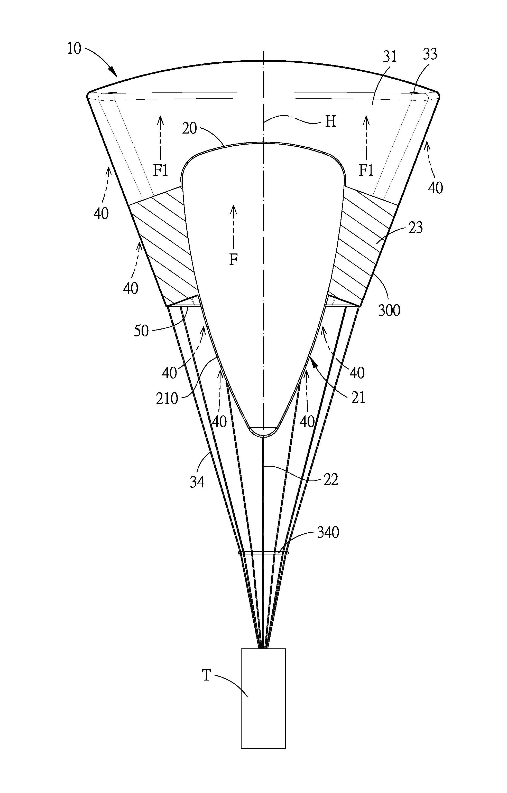
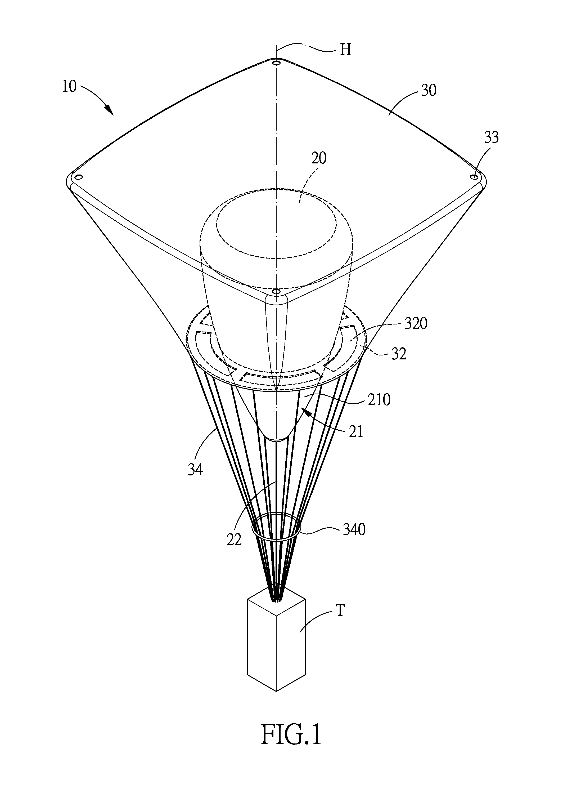
[0021]Referring to FIG. 1, a coaxial double layer parachute 10 in accordance with the present invention comprises: an inner inflatable body 20 and an outer canopy 30. The inner inflatable body 20 is used to fill with helium and includes an air flow guiding round-nose) 21 at a lower portion of the inner inflatable body 20. The air flow guiding round-nose 21 is profiled an arc-shaped surface 210. A restricting cord 22 has one end connected to a bottom of the air flow guiding round-nose 21, and the other end connected to a payload T.

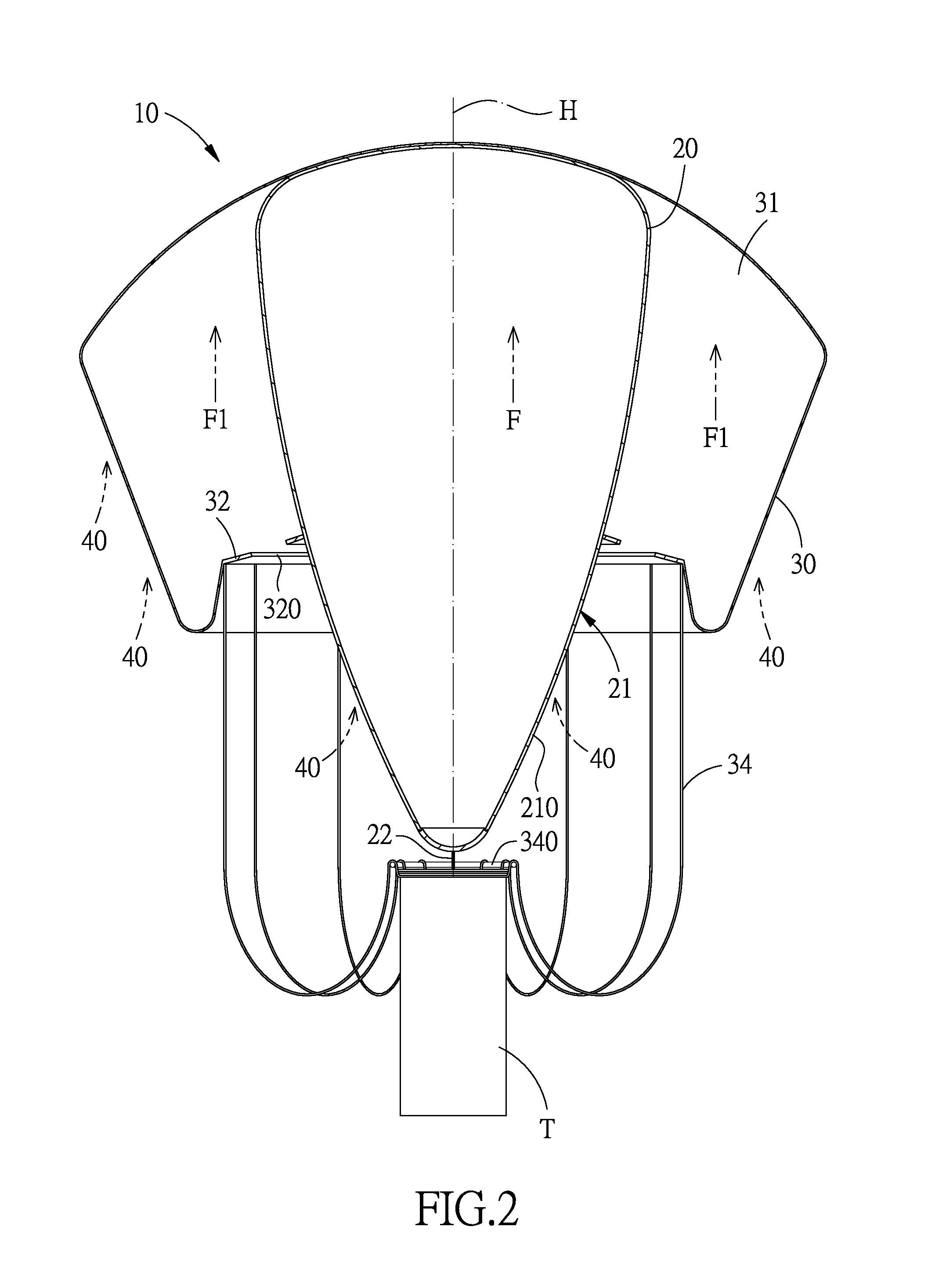
[0022]The outer canopy 30 covers the inner inflatable body 20 which is disposed inside the outer canopy 30 while between the outer canopy 30 and the inflatable body 20 is defined an inflation space 31. The bottom surface 32, been formed from the lower portion of the outer canopy 30 and provided with a plurality of air inlets 320 which are annularly arranged, is directly connected to the air flow guiding round-nose 21 of the inner inflatable body 20. At each...

second embodiment

[0027]Referring then to FIG. 4, a coaxial double layer parachute 10 in accordance with the present invention comprises: an inner inflatable body 20, an outer canopy 30 and a formed circular plate 50.

[0028]The inner inflatable body 20 is used to fill with helium and provided with a plurality of fabric panels 23 around the outer surface of the inner inflatable body 20, and an air flow guiding round-nose 21 at lower portion of the inner inflatable body 20. The air flow guiding round-nose 21 is profiled an arc-shaped surface 210. A restricting cord 22 has one end connected to a bottom of the air flow guiding round-nose 21, and the other end connected to a payload T.

[0029]The outer canopy 30 covers the inner inflatable body 20 which is disposed inside the outer canopy 30 while the outer canopy 30 and the inflatable body 20 is defined an inflation space 31. At each of four corners of the top surface of the outer canopy 30 is formed an air exhaust port 33, and to the periphery of the botto...


PUM


Abstract

A coaxial double layer parachute includes an inner inflatable body and an outer canopy which are located along a central axis. Since the inner inflatable body is filled with helium to generate a first buoyance, the inner inflatable body can be obviously lifted to a certain height. When a payload connected to the inner inflatable body and the outer canopy with parachute cords falls, the ambient air flows will enter the inflation space through the annular air inlets to produce a second buoyance, which makes the outer canopy open completely. Hence, a secure descending task from even a very low height can be fulfilled if the coaxial double layer parachute can employed. Apparently, the coaxial double layer parachute can be mainly applied to fire and earthquake rescue actions in the cities when low height deployments, risk-free parachuting, and less complicated manual operation are required.

Description

BACKGROUND OF THE INVENTION[0001]Field of the Invention[0002]The present invention relates to a parachute, and more particularly to a coaxial double layer parachute which can be mainly applied to fire and earthquake rescue actions in the cities when low height deployments, risk-free parachuting, and less complicated manual operation are required.[0003]Description of the Prior Art[0004]Parachute is an aerodynamic decelerator which is fixed to a payload by a connecting member. Hence, the parachute can be deployed to slow down the falling speed of the payload by creating a drag.[0005]However, the deployment of most parachutes requires a great height to carry out parachuting. Second, failure of an operational parachute extraction system causing fatalities and injuries leads to less trust in using parachuting decelerator as a fire escape device. Third, relatively complicated manual operation and skills are required.[0006]The present invention has arisen to practically amend the afore-des...

Claims


Application Information

Patent Timeline
Patent Type & Authority Applications(United States)
IPC IPC(8): B64D17/78B64D17/72B64D17/04
CPCB64D17/78B64D17/72B64D17/04
Inventor LIAO, SHUEH-CHIH
Owner LIAO SHUEH CHIH
Why Eureka
Try Eureka