Sonar transducer assembly

Active Publication Date: 2016-12-29
NAVICO HLDG
View PDF5 Cites 25 Cited by
  • Summary
  • Abstract
  • Description
  • Claims
  • Application Information

AI Technical Summary

Benefits of technology

[0005]Some embodiments of the present invention provide sonar systems that are configured to enable rotation of a transducer array that includes at least two transducer elements. In some embodiments, the transducer array may be mounted to a trolling motor capable of being rotated. The transducer elements can be positioned to enable use of interferometry to obtain angle information regarding sonar returns. The angle and range of each sonar return can be use

Problems solved by technology

However, some sonar systems may be limited in their capabilities, such as requiring a watercraft to actively

Method used


Image

  • Sonar transducer assembly
  • Sonar transducer assembly
  • Sonar transducer assembly

Examples


example rotational mounting

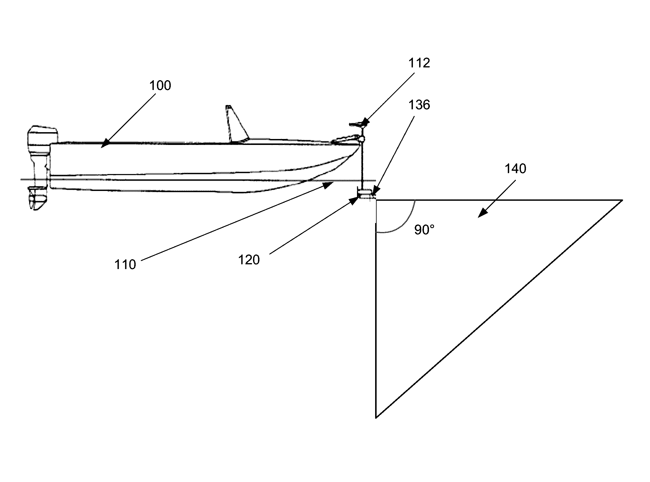
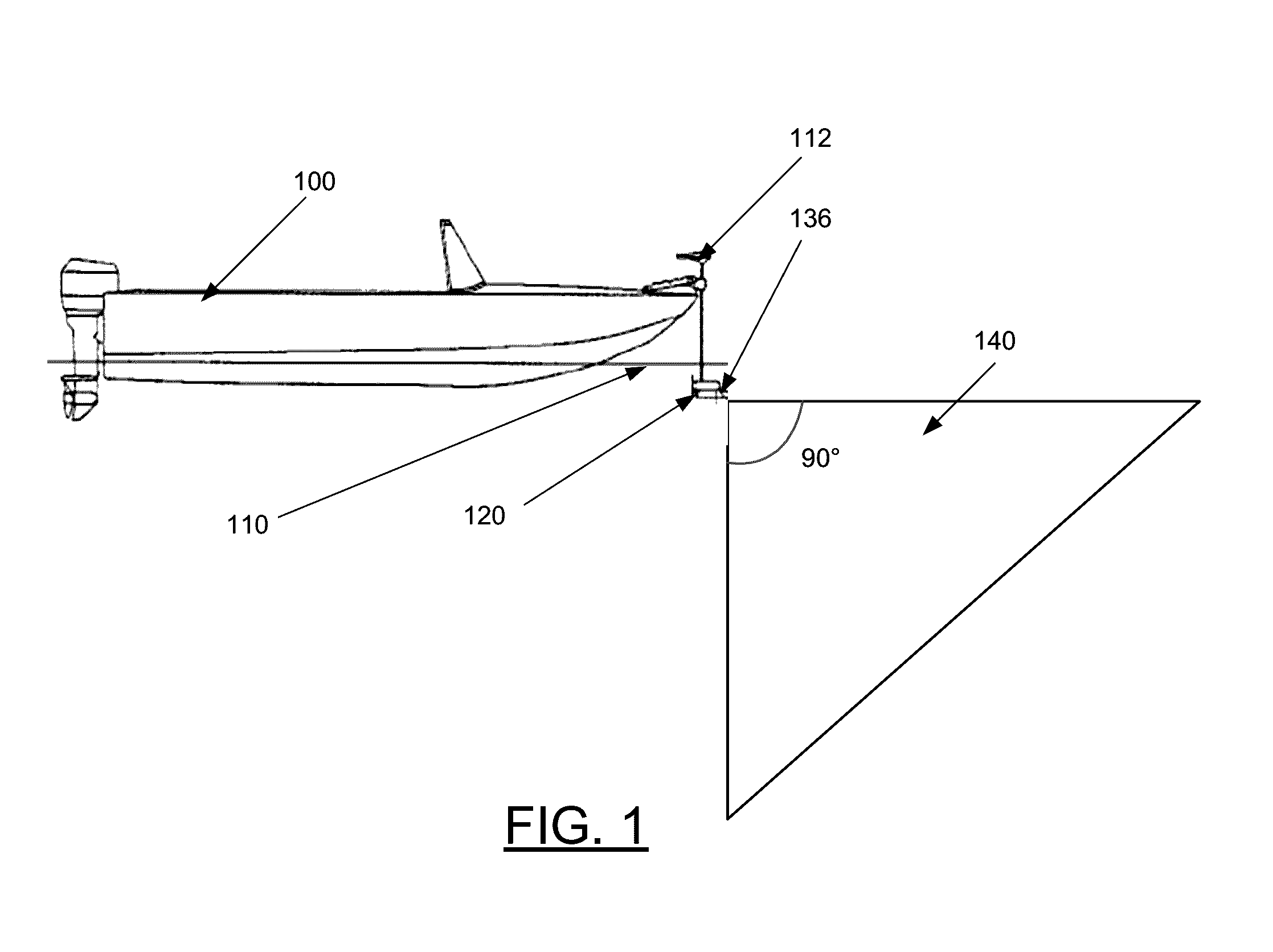
[0054]As noted above, in some embodiments, the sonar transducer assembly 36 may comprise a housing that is mountable to a watercraft (or device mounted to a watercraft) so as to enable rotation of the transducer elements with respect to the watercraft. With reference to FIGS. 4A, 4B, and 4C, the transducer assembly 136 may be mounted to a trolling motor 120 such that the transducer assembly 136 (and the transducer elements contained therein) may be rotated up to 360 degrees with respect to the watercraft 100 along with the trolling motor 120. For example, with reference to FIG. 4A, the transducer assembly 136 and the trolling motor 120 may be aimed to transmit sonar pulses and / or receive sonar returns (e.g., defined by the beam pattern 140) generally forward from the watercraft 100. However, with reference to FIG. 4C, the sonar transducer assembly 136 may be rotated (e.g., along arrow A) such that the transducer assembly 136 is aimed to transmit sonar pulses and / or receive sonar ret...

example image processing

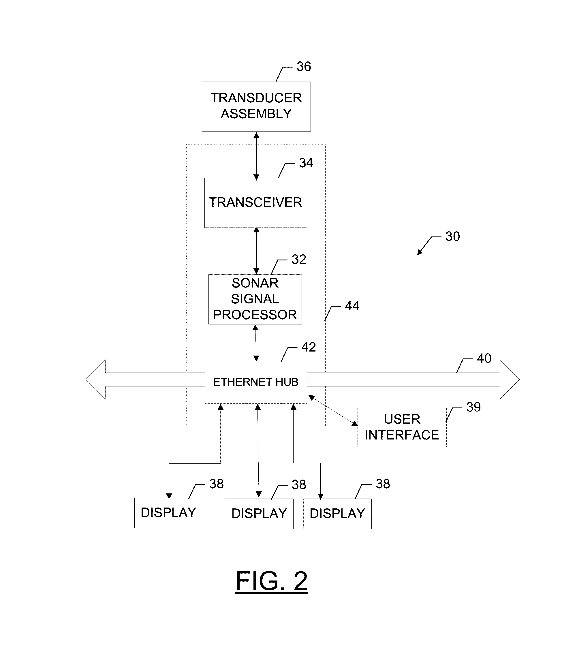
[0058]As noted above, some embodiments of the present invention comprise a sonar signal processor. In some embodiments, the sonar signal processor is configured to receive sonar return data resulting from the transducer elements in the transducer array. Additionally, in some embodiments, the sonar signal processor is further configured to generate one or more images (or image data corresponding to one or more images) of the underwater environment based on the received sonar return data and / or other information (e.g., a detected heading from the heading sensor).

[0059]In some embodiments, the sonar signal processor is configured to generate 2D radar-like sonar image data, 2D forward looking sonar image data, and / or 3D sonar image data. As detailed herein, the corresponding 2D radar-like image, 2D forward looking image, and / or 3D image can be displayed to a user on a display (e.g., separately, split-screen mode, etc.). Additionally, in some embodiments, other information (e.g., depth, ...

example 2d

Forward Looking Imaging

[0065]In some embodiments, the sonar signal processor is configured to generate 2D forward looking sonar image data corresponding to a 2D forward looking image of the underwater environment. In some embodiments, the 2D forward looking image is formed as a composite of sonar returns respectively arranged as the sonar returns are captured (e.g., in waterfall form).

[0066]The sonar returns used to generate the corresponding 2D forward looking sonar image data are received with at least a first transducer element and a second transducer element. The sonar returns define a range. Interferometry between the corresponding first sonar returns from the first transducer element and second sonar returns from the second transducer element is used to define an angle associated with each sonar return. Depending on the orientation of the transducer elements, two transducer elements stacked with respect to each other in a direction can be used to determine an angle of a sonar ...


PUM

PropertyMeasurementUnit
Angleaaaaaaaaaa
Angleaaaaaaaaaa
Angleaaaaaaaaaa

Abstract

Sonar systems and associated methods are provided herein for sonar image generation. The sonar system is configured to enable rotation of a transducer array that includes at least two transducer elements. The transducer array may be mounted to a trolling motor capable of being rotated. The transducer elements can be positioned to enable use of interferometry to obtain angle information regarding sonar returns. The angle and range of each sonar return can be used to form images, such as a 2D forward looking image of the underwater environment. A heading detector can be used to obtain a heading of the transducer elements to enable creation of a 2D radar-like image of the underwater environment. Additionally, the heading, angle, and range of the sonar returns can be used to form a 3D image of the underwater environment.

Description

RELATED APPLICATIONS[0001]This application claims priority to and is a continuation-in-part application of U.S. application Ser. No. 13 / 827,329, entitled “Sonar Transducer Assembly”, filed on Mar. 14, 2013, which is hereby incorporated by reference in its entirety. This application also claims priority to and the benefit U.S. Provisional Application No. 62 / 024,416, entitled “Forward Looking Sonar Display”, filed on Jul. 14, 2014, and U.S. Provisional Application No. 62 / 128,641, entitled “Methods And Apparatuses for Reconstructing a 3D Sonar Image”, filed on Mar. 5, 2015, both of which are hereby incorporated by reference in their entireties.FIELD OF THE INVENTION[0002]Embodiments of the present invention relate generally to sonar systems and, more particularly, to a sonar system configured for imaging of an underwater environment relative to a watercraft.BACKGROUND OF THE INVENTION[0003]Sonar (SOund Navigation And Ranging) has long been used to detect waterborne or underwater object...

Claims


Application Information

Patent Timeline
IPC IPC(8): G01S15/89G01S7/62G01S15/96
CPCG01S15/8902G01S7/6245G01S15/96B63B2201/18B63H20/007G01S15/89Y10T29/49002
Inventor PROCTOR, ALAN LEEPARKS, DAVID AUSTINHORNER, RONALD JOE
Owner NAVICO HLDG
Why Eureka
Try Eureka