Floating memristor emulator

Inactive Publication Date: 2016-12-29
KING FAHD UNIVERSITY OF PETROLEUM AND MINERALS
View PDF0 Cites 17 Cited by
  • Summary
  • Abstract
  • Description
  • Claims
  • Application Information

AI Technical Summary

Benefits of technology

The patent describes a new circuit that uses simple components to create an emulator of a memristor, which is a type of device used in FM demodulators. The circuit has low power consumption, is cost-effective, and easy to implement. The technical effect of this patent is the demonstration of the functionality of the new circuit in an FM demodulator, confirming the performance of the new technology.

Problems solved by technology

However, only few floating memristor emulators are available in the literature.
Those few designs have numerous components, which present size and power consumption problems.

Method used


Image

  • Floating memristor emulator
  • Floating memristor emulator
  • Floating memristor emulator

Examples


Embodiment Construction

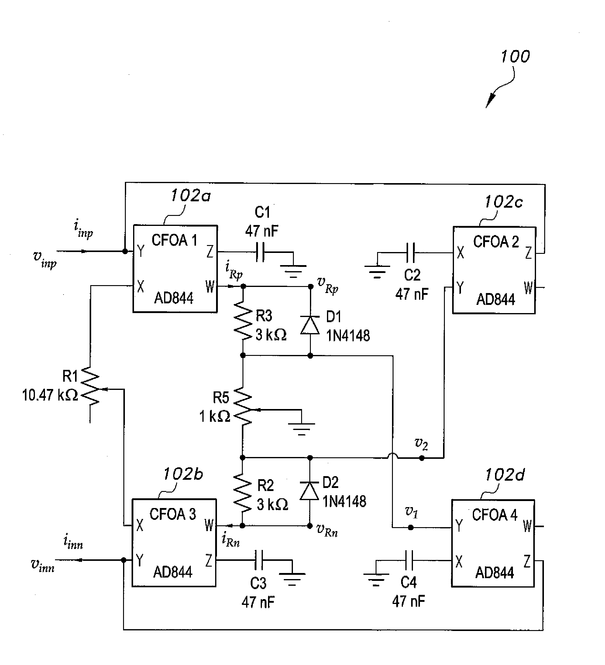
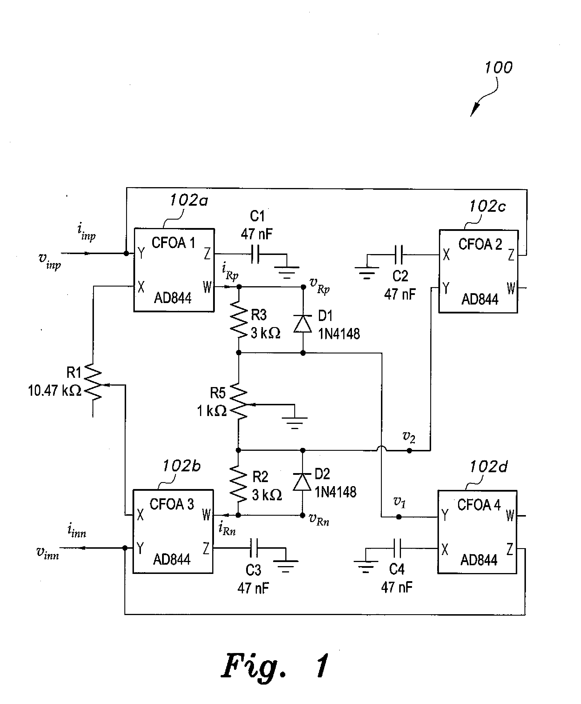
[0022]The present floating memristor emulator circuit includes four current feedback operational amplifiers (CFOA's 102a, 102b, 102c, and 102d), configured as shown in FIG. 1. The first 102a, second 102c, third 102b, and fourth 102d current feedback operational amplifiers (CFOAs), each have y, x, z, and w terminals. The y terminal of first CFOA1102a is connected two the z terminal of the second CFOA2102c. The y terminal of the third CFOA3102b is connected to the z terminal of the fourth CFOA4102d. A differential voltage input, vinp, vinn is formed from the y terminals of the first and third CFOAs (102a, 102b). The x terminals of CFOA1102a and CFOA3102b are in operable communication with each other. For example, a potentiometer R1 may be connected between the x terminals of CFOA1102a and CFOA3102b (the wiper portion being connected to CFOA3102b). Grounded capacitors C1 through C4 are connected to their respective CFOAs (102a, 102c, 102b, and 102d). A parallel combination (R3 and D1) ...


PUM


Abstract

The floating memristor emulator is based on a circuit implementation that uses grounded capacitors and CFOAs in addition to combinations of diodes and resistors to provide the required nonlinearity and time constants. This circuit results in low power consumption, cost reduction and ease of implementation because it avoids the use of multipliers, ADCs and RDACs. The present circuit is used in an FM demodulator, which exploits the frequency-dependence of the memristance. Successful use in the FM demodulator confirmed the functionality of the present floating memristor emulator circuit.

Description

BACKGROUND OF THE INVENTION[0001]1. Field of the Invention[0002]The present invention relates to memristors, and particularly to a floating memristor emulator that can be used in frequency-to-voltage conversion.[0003]2. Description of the Related Art[0004]Since its inception, several emulators have been presented for the grounded memristor. However, only few floating memristor emulators are available in the literature. Those few designs have numerous components, which present size and power consumption problems.[0005]Thus, a floating memristor emulator solving the aforementioned problems is desired.SUMMARY OF THE INVENTION[0006]The floating memristor emulator is based on a circuit implementation that uses grounded capacitors and CFOAs in addition to combinations of diodes and resistors to provide the required nonlinearity and time constants. This circuit results in low power consumption, cost reduction and ease of implementation because it avoids the use of multipliers, ADCs and RDA...

Claims


Application Information

Patent Timeline
IPC IPC(8): G06F17/50G06F17/10
CPCG06F17/10G06F17/5036G11C13/0007H03D3/34H03D3/00G06F30/367
Inventor ABUELMA'ATTI, MUHAMMAD TAHERKHALIFA, ZAINULABIDEEN JAMAL
Owner KING FAHD UNIVERSITY OF PETROLEUM AND MINERALS
Why Eureka
Try Eureka