Apparatus and method for controlling the conditions of at least one band circulating in a paper making machine and paper making machine comprising said apparatus

Active Publication Date: 2017-01-05
GIUSEPPE CRISTINI
View PDF0 Cites 2 Cited by
  • Summary
  • Abstract
  • Description
  • Claims
  • Application Information

AI Technical Summary

Benefits of technology

[0008]One object of the present invention is therefore to provide an apparatus for controlling the conditions of at least one band circulating i

Problems solved by technology

Said apparatus, however, detects data that cannot be inter-correlated for the purpose of making a reliable diagnosis of the condition of the circulating band.
An ina

Method used


Image

  • Apparatus and method for controlling the conditions of at least one band circulating in a paper making machine and paper making machine comprising said apparatus
  • Apparatus and method for controlling the conditions of at least one band circulating in a paper making machine and paper making machine comprising said apparatus
  • Apparatus and method for controlling the conditions of at least one band circulating in a paper making machine and paper making machine comprising said apparatus

Examples


second embodiment

[0077]FIG. 3 illustrates a portion 101 of a paper making machine 100 according to a

[0078]The portion 101 illustrated in FIG. 2 is relative to a pressing section of a paper sheet 99 normally between a forming section 102 (partially illustrated) and a drying section (not illustrated).

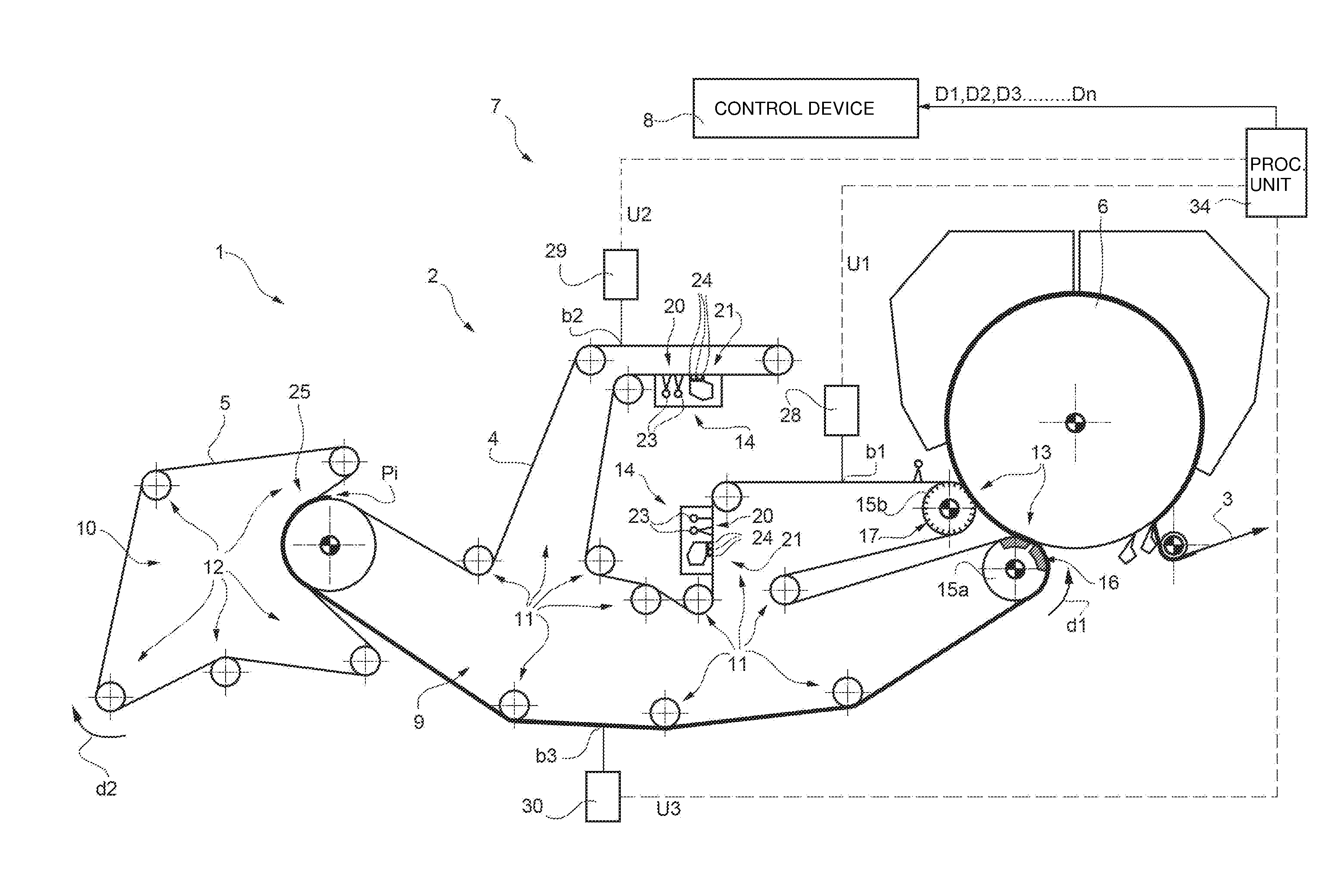
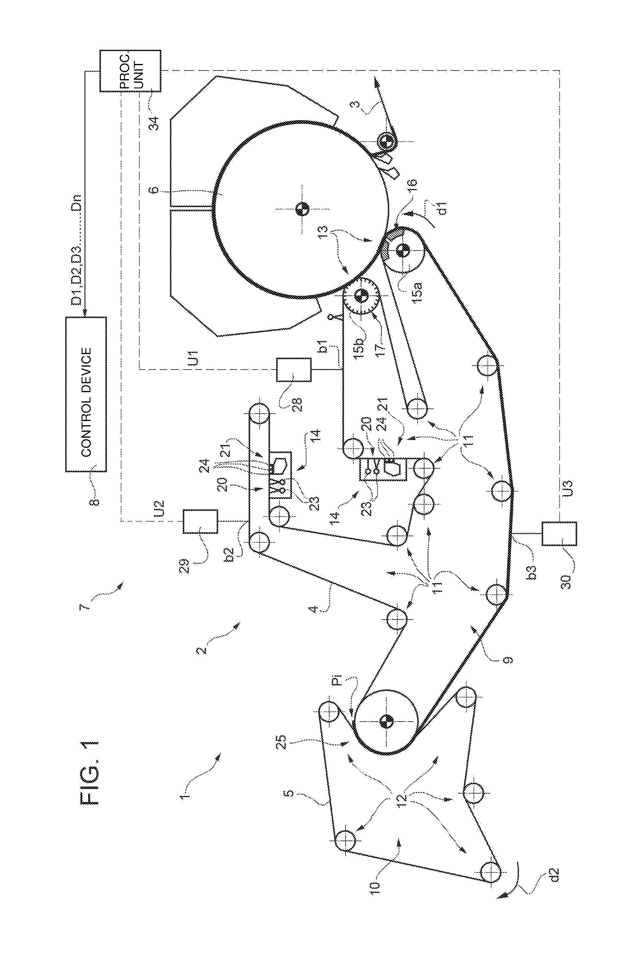
[0079]The portion 101 of the machine 100 comprises four bands 103104105106 circulating along respective closed annular paths, a first static cylinder 108, a second static cylinder 109, a control device 111 and an apparatus 112 for controlling the conditions of at least one of the bands 103104105106 circulating in the machine 1 according to the present invention (partially illustrated in FIG. 3 and more fully in FIG. 4).

[0080]It is understood that the pressing section of the paper making machine 1 can comprise a variable number of circulating bands and more than two static cylinders according to the type of machine and the scheduled operating configurations.

first embodiment

[0081]Analogously to what is described for the first embodiment, the machine comprises support means 113114115116 configured to support the four bands 103104105106 respectively along the respective closed annular paths.

[0082]The support means 113114115116 are defined by respective pluralities of idler rollers 123124125126.

[0083]The idler rollers 123 are moved so that the band 103 runs along the path in an anticlockwise direction R1, as indicated by the arrow in FIG. 3.

[0084]The idler rollers 124 are moved so that the band 104 runs along the path in a clockwise direction R2, as indicated by the arrow in FIG. 3.

[0085]The idler rollers 125 are moved so that the band 105 runs along the path in a clockwise direction R3, as indicated by the arrow in FIG. 3.

[0086]The idler rollers 126 are moved so that the band 106 runs along the path in an anticlockwise direction R4, as indicated by the arrow in FIG. 3.

[0087]The machine 1 further comprises a first pressing station 130, defined by a idler ...


PUM


Abstract

An apparatus for controlling the conditions of at least one band circulating in a paper making machine along a circulation direction is provided with at least one first detecting device configured to detect at least one first parameter indicative of the humidity of the band and positionable in a first position between a pressing station and a conditioning station of the paper making machine; at least one second detecting device configured to detect at least one second parameter indicative of the humidity of the band and positionable in a second position downstream of the conditioning station; and at least one processing unit configured to determine at least one datum indicative of the condition of the band on the basis of the first parameter indicative of the humidity and of the second parameter indicative of the humidity.

Description

TECHNICAL FIELD[0001]The present invention concerns an apparatus and a method for controlling the conditions of at least one band circulating in a paper making machine and paper making machine comprising said apparatus.BACKGROUND ART[0002]As is known, the traditional paper making machines are provided with one or more bands (commonly known as felts) circulating along closed annular paths, by means of which the paper being formed is transported and processed.[0003]Each section of the machine has, in general, a specific type of band.[0004]To obtain good quality paper, it is important to assess the conditions of the band in each section, in addition to monitoring the conditions of the material transported on it.[0005]The conditions of the band, in terms of absorption of water, transport of water and permeability to water, affect the quality of the paper sheet, in particular during the pressing phase. It is therefore important to monitor the conditions of the band, in particular during ...

Claims


Application Information

Patent Timeline
IPC IPC(8): D21G9/00D21F7/12D21F1/32
CPCD21F1/32D21F7/12D21G9/0036
Inventor CANALI, LUCACRISTINI, GIOVANNI
Owner GIUSEPPE CRISTINI
Why Eureka
Try Eureka