
Method for diagnosing fault of wheel speed sensor of vehicle, and corresponding controller and vehicle

A wheel speed sensor and fault diagnosis technology, applied in the vehicle field, can solve problems such as false detection and failure to detect faults, and achieve the effect of preventing false start and misoperation

Active Publication Date: 2014-05-21
BOSCH AUTOMOTIVE PROD SUZHOU
View PDF7 Cites 23 Cited by
  • Summary
  • Abstract
  • Description
  • Claims
  • Application Information

AI Technical Summary

Problems solved by technology

A threshold that is too high may make it impossible to detect real faults; a threshold that is too low may produce false detections

Method used


Image

  • Method for diagnosing fault of wheel speed sensor of vehicle, and corresponding controller and vehicle

Examples


Embodiment Construction

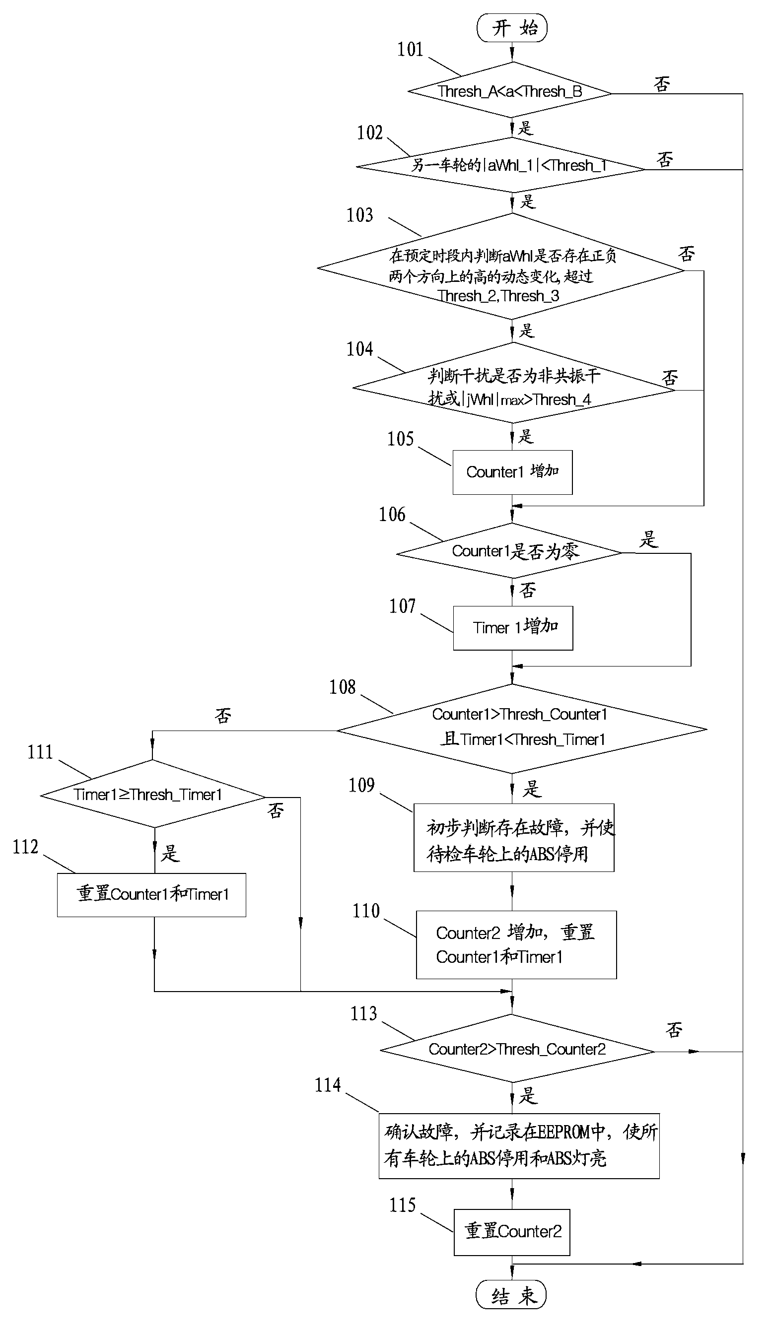
[0029] As a device for measuring the rotational speed of a wheel, the wheel speed sensor is often affected by various external factors during operation. For example, compared with the situation when the wheel passes on a flat road, the bump vibration when the wheel passes over an uneven road surface will cause some changes in the output signal of the wheel speed sensor installed thereon. In other words, even if the wheel speed sensor is completely normal without any failure, the output signal of the wheel speed sensor when the wheel passes over an uneven road will be significantly different from the output signal of the wheel speed sensor when the wheel passes over a flat road. This difference can be called Interference or noise, which may cause false activation and false operation of the ABS or ESP system. Moreover, the wheel speed sensor itself may also have some abnormal faults, so that the output signal of the wheel speed sensor cannot reflect the actual driving conditions...


PUM


Abstract

The invention relates to a method for diagnosing fault of a wheel speed sensor of a vehicle, wherein the vehicle is provided with at least two wheels, each of which is provided with a wheel speed sensor. The method comprises the steps of obtaining the output signal of the wheel speed sensor to be examined on the wheel to be examined and the output signal of other wheel speed sensor on at least one other wheel, and diagnosing the fault of the wheel speed sensor to be examined based on the output signal of the wheel speed sensor to be examined on the wheel to be examined and the output signal of the other wheel speed sensor on the at least one other whee. The invention also relates to a controller for a vehicle and a vehicle comprising the controller. The method can be implemented in real time and is capable of diagnosing the fault successfully and preventing false start and misoperation of an ABS (Anti-lock Braking System) and / or an ESP (Electronic Stability Program) reliably, and therefore, reliable control on the wheel is further improved, and the operating performance of the vehicle is improved.

Description

technical field [0001] The present invention relates to a method for diagnosing a malfunction of a wheel speed sensor of a vehicle, a controller for performing the method, and a vehicle including the controller. Background technique [0002] The ABS (anti-lock braking system) or ESP (electronic stability system) of modern cars are often equipped with wheel speed sensors, and the most commonly used ones are electromagnetic induction wheel speed sensors. The electromagnetic induction wheel speed sensor is mainly composed of permanent magnets, magnetic poles, coils and ring gears. When the ring gear rotates in the magnetic field, the gap between the tooth top of the ring gear and the electrode changes at a certain speed, which causes the reluctance in the magnetic circuit to change, so that the magnetic flux increases and decreases periodically, and then the two sides of the coil The terminal produces an induced voltage proportional to the increase and decrease speed of the ma...

Claims


Application Information

Patent Timeline
Patent Type & Authority Applications(China)
IPC IPC(8): G01P21/02B60T17/22
Inventor 俞雷兵
Owner BOSCH AUTOMOTIVE PROD SUZHOU
Learn More