Diagnostic system and method for a valve, especially a check valve of a positive displacement pump

a technology of positive displacement and diagnostic system, which is applied in the direction of positive displacement liquid engines, instruments, machines/engines, etc., can solve the problems of reduced measurement sensitivity, increased measurement expenditure, and possible false alarms, and achieve the effect of low expenditure for measuring system components

Inactive Publication Date: 2009-11-24
SIEMENS AG
View PDF11 Cites 22 Cited by
  • Summary
  • Abstract
  • Description
  • Claims
  • Application Information

AI Technical Summary

Benefits of technology

[0004]A diagnostic system is known from DE 199 24 377 A1 for a valve which can be actuated by a position controller via a drive, which features a device for recording, storage and evaluation of solid-borne sound spectra measured at the valve. To make an especially reliable valve diagnosis possible a solid-borne sound spectrum of recorded for a slightly open, intact valve can be stored in the device for recording, storage and evaluation. For diagnosis a solid-borne sound spectrum recorded for a closed valve is compared to the spectrum stored and the similarity is employed as a criterion for the lack of seal of the valve. The known diagnostic method has the disadvantage that an exact positionability of the closing element is required so that a comparison spectrum for a slightly open, intact valve can be recorded for simulation of a valve leakage. It is thus not applicable to a plurality of valve types, for example check valves for positive displacement pumps.
[0009]For a reliable detection of a leakage the leakage noise for a closed valve and the leakage noise for an open file are recorded almost simultaneously and compared with one another. The two measurement times can be all the closer to one another the shorter the gap is between the two states “valve open” and “valve closed”. In the special case of an application of the diagnostic system to check valves in oscillating positive displacement pumps the valves are periodically opened and closed. Since the two check valves assume it precisely opposite states at specific times the leakage noise can be recorded at one valve while at precisely the same time the plant noise is recorded at the other valve. The noises can be assigned to the relevant valve state in a simple way by suitable signal processing. In principle the diagnosis can however be performed in this case with just one solid-borne sound sensor which then records the leakage noise and the plant noise in the closed or open state of the same valve respectively in chronological order. However in this case the new diagnostic system has the advantage that it is largely insensitive to gradual changes in operating conditions.
[0010]Correspondingly the new diagnostic system and a new diagnostic method can be applied for valves in piston compressors which operate in accordance with a largely similar principle.
[0011]The diagnostic system has an especially low sensitivity to wide variations in operating conditions if the first value and the second value of the characteristic variable which are compared with each other are determined on the basis of the sound signal last recorded in the closed or the open state. In this case it can be assumed that the plant's noises in the intervening period have in any event only changed slightly and thereby barely affect the diagnosis result in any way.
[0012]In an application of the system to diagnosis of a check valve of a positive displacement pump it is advantageously sufficient to have especially low expenditure for measuring system components if the evaluation device is embodied such the respective state of the valve can be determined by it on the basis of the recorded sound signal. In this case no further means for recording the position of the closing element is necessary. The system can make do with just one sound recorder for a measuring point.

Problems solved by technology

If they become larger there is a possibility of a false alarm being triggered.
If the plant noises become smaller during the course of operation this leads to a reduction in measurement sensitivity since the threshold value predetermined was too high.
In addition the measurement of the sound level in the good state involves additional expenditure during commissioning.
With operating conditions which vary greatly for the valve under investigation the diagnostic method cannot be employed because the plant sounds are heavily dependent on the operating conditions.
For check valves of positive displacement pumps especially the method cannot be used under these circumstances since measurements have shown that the system noise always depends on the operating pressure and this rises by around 20 dB if there is a change in pressure from 5 to 50 bar.

Method used


Image

  • Diagnostic system and method for a valve, especially a check valve of a positive displacement pump
  • Diagnostic system and method for a valve, especially a check valve of a positive displacement pump
  • Diagnostic system and method for a valve, especially a check valve of a positive displacement pump

Examples


Embodiment Construction

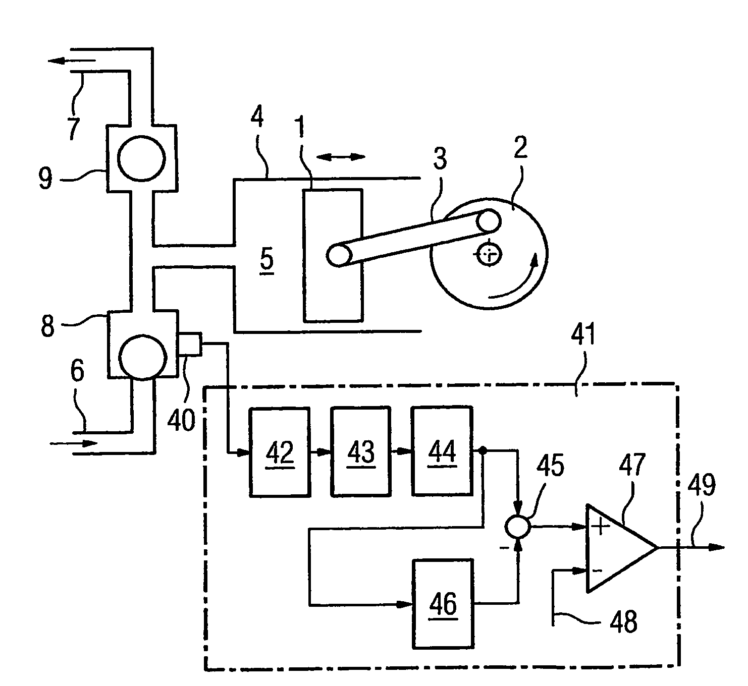
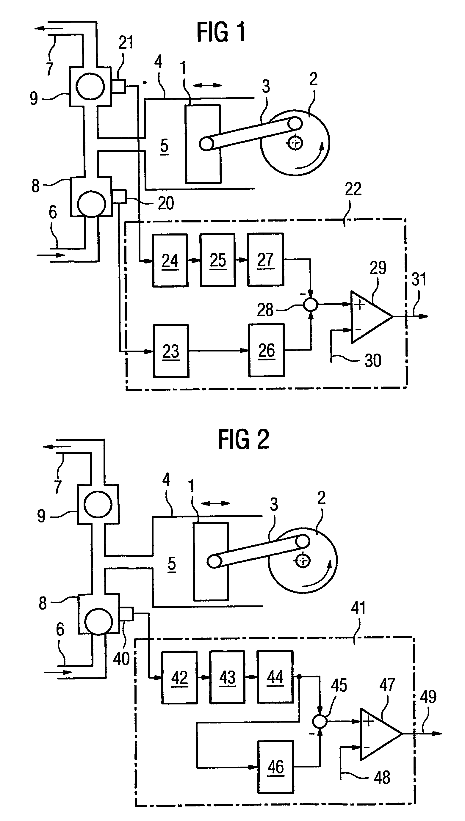
[0018]FIGS. 1 and 2 each show a positive displacement pump along with its basic layout. The same parts are identified by the same reference symbols in the two Figures. The functional principle of a positive displacement pump is thus explained below with reference to the example shown in FIG. 1. A piston 1 is moved alternately left and right in a cylinder 4 by a crankshaft 2 with a connecting rod 3. This produces a variable volume 5 in cylinder 4. Check valves 8 or 9 are arranged in an inlet 6 and in an outlet 7 to this volume 5 respectively. These check valves are frequently also referred to as inlet or outlet valves. If the volume 5 reduces as shown in the phase depicted in FIG. 1, check valve 9 opens and a medium to be delivered flows out to the outlet 7. At the same time valve 8 is closed. With an enlargement of the volume 5 on the other hand, valve 8 opens so that the medium can flow into the inside of cylinder 4. The valve 9 closes the outlet 7 and thereby prevents flowback of ...


PUM


Abstract

A diagnostic system and method for a valve, especially a check valve of a positive displacement pump, including at least one solid-borne sound sensor is provided. A first value of a parameter of a sound signal recorded in the closed state of the valve and a second value of a parameter of a sound signal recorded in the open state of a valve are determined essentially. A signal indicating a disturbance is issued if the deviation between the first value and the second value exceeds a predefined threshold value, resulting in particularly good insensitivity.

Description

[0001]The invention relates to a diagnostic system as well as to a diagnostic method for a valve, especially a check valve of a positive displacement pump.CROSS REFERENCE TO RELATED APPLICATIONS[0002]This application is the US National Stage of International Application No. PCT / EP2004 / 005193, filed May 14, 2004 and claims the benefit thereof. The International Application claims the benefits of German application No. 10322194.8 DE filed May 16, 2003, both of the applications are incorporated by reference herein in their entirety.FIELD OF INVENTION[0003]In many areas of process control and energy technology the fault-free operation of a system depends on the smooth functioning of the control and check valves used. To avoid cost-intensive, irregular interruptions to operation, damage to valves should where possible be detected right at the outset, that is before a failure of the valve can result in a shutdown of the plant. For example defective valve seats result in leakage flows whic...

Claims


Application Information

Patent Timeline
Patent Type & Authority Patents(United States)
IPC IPC(8): G01M19/00G01M99/00F04B51/00F16K37/00G01M13/02
CPCF04B51/00F16K37/0083G01M13/028
Inventor ENS, WOLFGANGPUTTMER, ALF
Owner SIEMENS AG
Why Eureka
Try Eureka