Rotational structure for rotary knob

a technology of rotational structure and rotary knob, which is applied in the direction of instruments, mechanical control devices, shock absorbers, etc., can solve the problems of difficult to provide a suitable magnitude of rotational resistance to the rotary knob, and achieve the effect of reducing the influence of variation in the dimensions reducing the backlash of the rotary knob, and suitable magnitude of rotational resistan

Active Publication Date: 2017-01-05
ONKYO TECH KK
View PDF4 Cites 1 Cited by
  • Summary
  • Abstract
  • Description
  • Claims
  • Application Information

AI Technical Summary

Benefits of technology

[0010]According to the rotary knob rotational structure of one aspect of the present invention, the annular sheet interposed between the device body and the attachment member contacts the body-side protrusion to warp toward the rotary knob. Accordingly, the rotary knob is biased in the direction away from the device body, and in this biased state, slides on the annular sheet such that the rotational resistance is provided to the rotary knob. With this configuration, the biasing force of the annular sheet can reduce backlash of the rotary knob while a suitable magnitude of rotational resistance can be provided to the rotary knob. Moreover, since the rotary knob is biased in the direction away from the device body in the state in which the annular sheet warps, variation in the dimensions of the rotary knob can be absorbed according to the degree of warpage of the annular sheet. As a result, the influence of variation in the dimensions of the rotary knob can be reduced.
[0011]Accordin...

Problems solved by technology

Thus, it is difficult to provide a suitable ma...

Method used


Image

  • Rotational structure for rotary knob
  • Rotational structure for rotary knob
  • Rotational structure for rotary knob

Examples


first embodiment

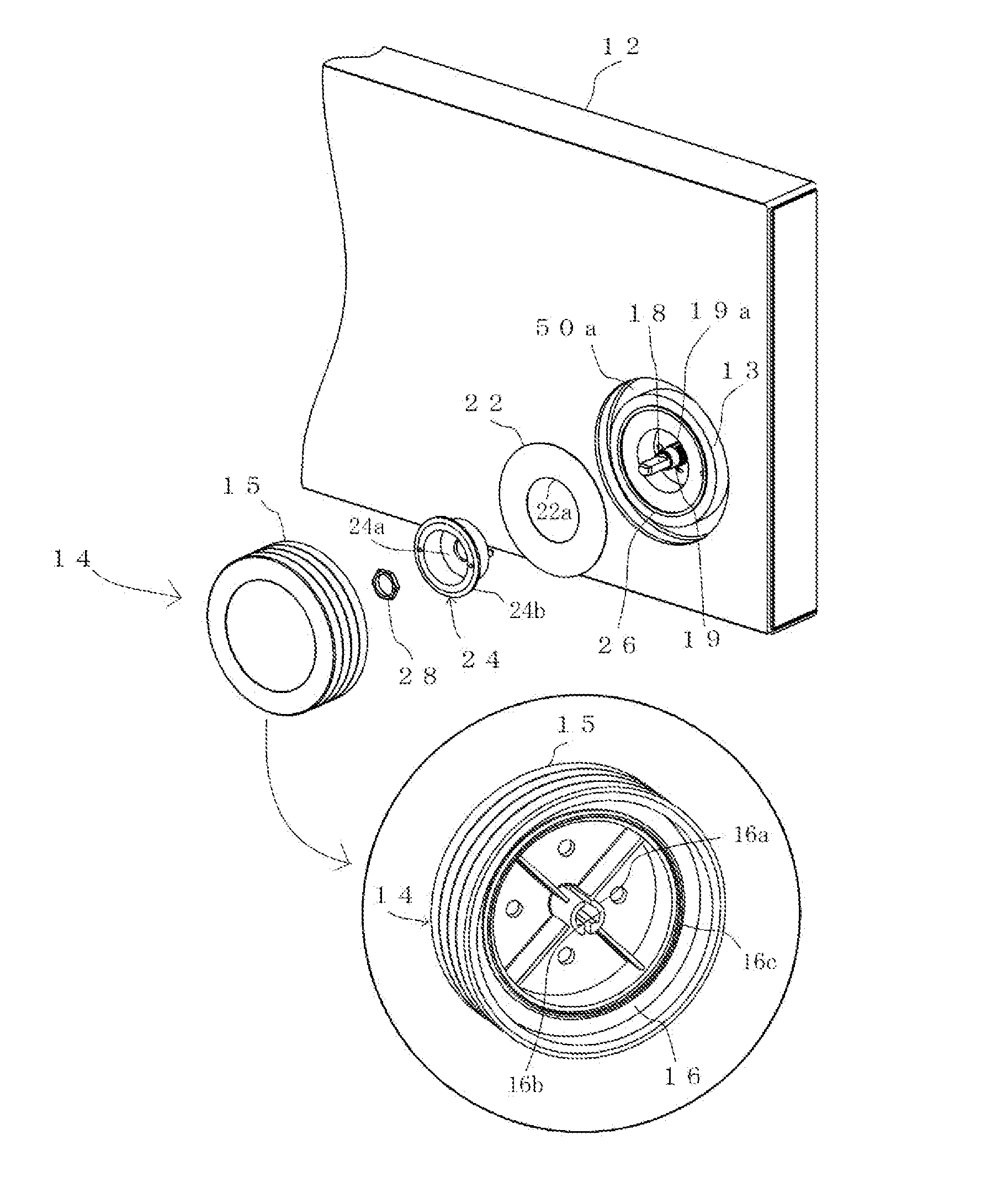
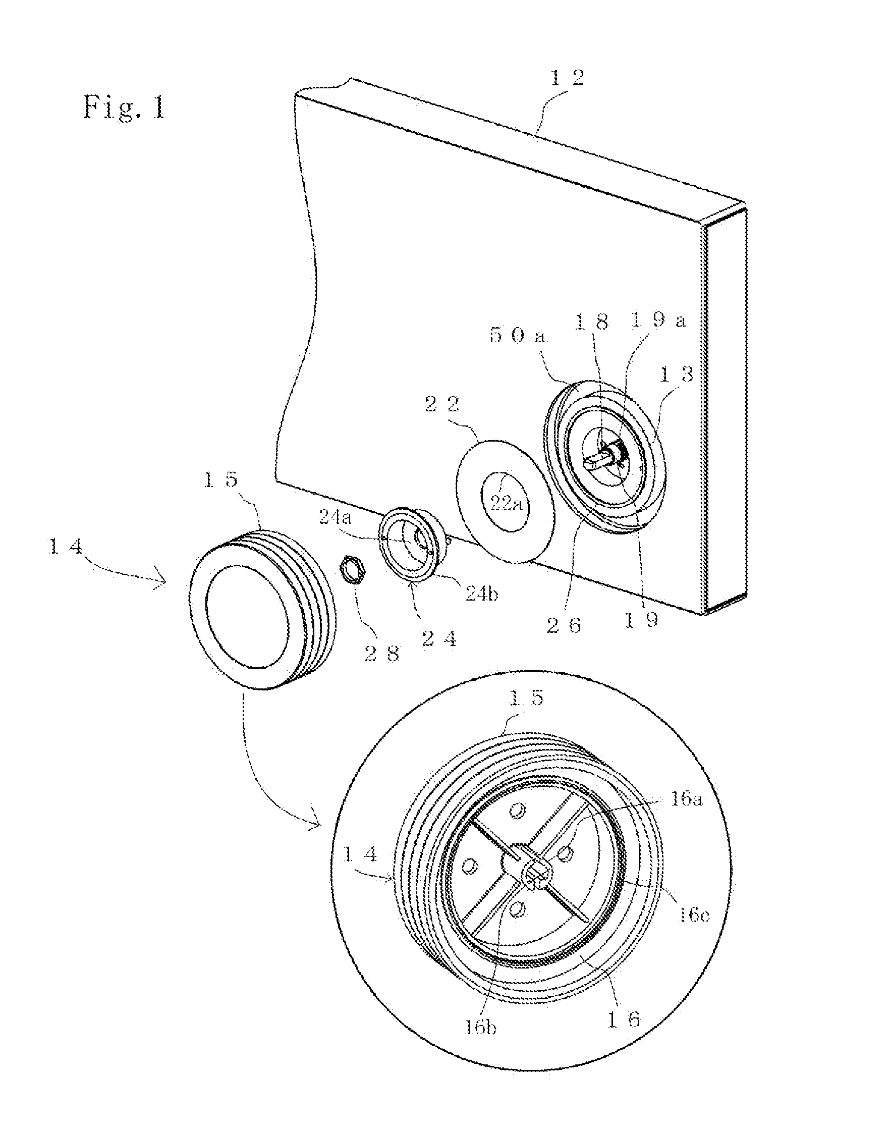
[0017]FIG. 1 is an exploded perspective view of an audio device having a rotary knob rotational structure of the present invention, and also partially illustrates a rotary knob configuration on the back side thereof.

[0018]In, e.g., a body of the audio device, a rotary knob 14 is rotatably attached to a rotary shaft 18 fixed to a front panel 12 and protruding from the front panel 12, and has the function of adjusting, e.g., the volume of sound according to rotational displacement of the rotary knob 14, as illustrated in FIG. 1.

[0019]In the device body, an annular protrusion 13 formed around the rotary shaft 18 is provided. An annular sheet 22 is interposed between the annular protrusion 13 and an attachment member 24, and is fixed to the device body.

[0020]The annular sheet 22 is made of thin resin having flexibility, such as polycarbonate, polypropylene, or polyimide, and is formed in a flat plate shape or a dish shape. As will be described later, the annular sheet 22 provides rotati...

second embodiment

[0035]According to the rotary knob rotational structure of the second embodiment, the annular sheet 22 interposed between the device body and the attachment member 32 warps toward the device body, and therefore, the annular sheet 22 can bias the rotary knob 14 in the direction away from the device body. Moreover, in such a biased state, the sliding portion 34 of the rotary knob 14 slides on the annular sheet 22 so that rotational resistance can be provided to the rotary knob 14. With this configuration, the biasing force of the annular sheet 22 can reduce backlash of the rotary knob 14 while a suitable magnitude of rotational resistance can be provided to the rotary knob 14. Moreover, since the rotary knob 14 is biased in the direction away from the device body in the state in which the annular sheet 22 warps, variation in the dimensions of the rotary knob 14 can be absorbed according to the degree of warpage of the annular sheet 22. Thus, the influence of variation in the dimension...


PUM


Abstract

Provided is a rotary knob rotational structure being less susceptible to the influence of variation in the dimensions of a rotary knob and reducing backlash of the rotary knob while providing a suitable magnitude of rotational resistance to the rotary knob.
The rotary knob rotational structure includes an annular sheet 22 interposed between a device body and the rotary knob 14, an attachment member 24 configured to attach a fixed portion 22a of the annular sheet 22 to the device body with the fixed portion 22a being interposed between the attachment member 24 and the device body, and a body-side protrusion 26 contacting the annular sheet 22 on the outside of the fixed portion 22a in the radial direction of the annular sheet 22 to warp the annular sheet 22 toward the rotary knob 14.

Description

BACKGROUND OF THE INVENTION[0001]1. Field of the Invention[0002]The present invention relates to a rotary knob structure provided at a device body, and particularly relates to a rotational structure configured to provide rotational resistance to a rotary knob.[0003]2. Description of the Related Art[0004]For example, a rotary knob is attached to a body of, e.g., an audio device to perform various types of operation. Some of these rotary knobs are configured to provide a weighted operational feeling in such a manner that rotational resistance is provided while the rotary knob is rotating.[0005]For example, JP-A-2010-257711 discloses a rotational structure for a rotary knob. In the rotational structure, an annular spacer as a stack of an elastic member and a sliding member is interposed in a clearance between a device body and the rotary knob. The annular spacer slides on the rotary knob to provide rotational resistance to the rotary knob. As a result, backlash of the rotary knob is re...

Claims


Application Information

Patent Timeline
IPC IPC(8): G05G5/03G05G1/10F16F13/02H01H19/14
CPCG05G1/08G05G23/00F16F13/02F16F2222/04F16F2236/04G05G1/10G05G5/03H01H19/14
Inventor YAMAGUCHI, SHINJI
Owner ONKYO TECH KK
Why Eureka
Try Eureka