Self-Measuring Wall Box Bracket

a self-measuring, wall box technology, applied in the field of brackets, can solve the problems of increasing the cost of the bracket, adding time and expense, and essentially unused, and achieve the effect of facilitating rapid and convenient installation of electric boxes and low cos

Active Publication Date: 2017-01-12
TERWILLEGER DAVID
View PDF5 Cites 14 Cited by
  • Summary
  • Abstract
  • Description
  • Claims
  • Application Information

AI Technical Summary

Benefits of technology

[0015]In the most preferred embodiments, the present invention relates to an apparatus and method for mounting an electrical outlet at a specified height between two wall studs with specified spacing in which the bracket itself is precisely dimensioned so that it can be used to determine the proper mounting height of the electrical box, which is a singular construction, and which comprises a rectangular body frame with an outlet box mounting frame and ears that extend outwardly from each corner. Each ear further comprises a screw hole, which is precisely positioned relative to the edges of the bracket, so that an electrical outlet may be installed at a specified height. To install an electrical box between two wall studs, the Self-Measuring Wall Box Bracket is first turned sideways so that the bottom edge of the body frame is vertical and a side of the bracket, which is now horizontal, is set on the floor. Next, the vertical bottom edge of the Self-Measuring Wall Box Bracket is aligned with a wall stud with the body frame positioned between the wall studs between which the outlet box is to be mounted. Slits located at the base of each ear on...

Problems solved by technology

These brackets usually require taking time consuming measurements to install, and measurement errors can contribute to reworking that may unnecessarily add time and expense to the installation of a single bracket.
However, using a singular construction usually has more benefits in the manufacturing proc...

Method used


Image

  • Self-Measuring Wall Box Bracket
  • Self-Measuring Wall Box Bracket
  • Self-Measuring Wall Box Bracket

Examples


Embodiment Construction

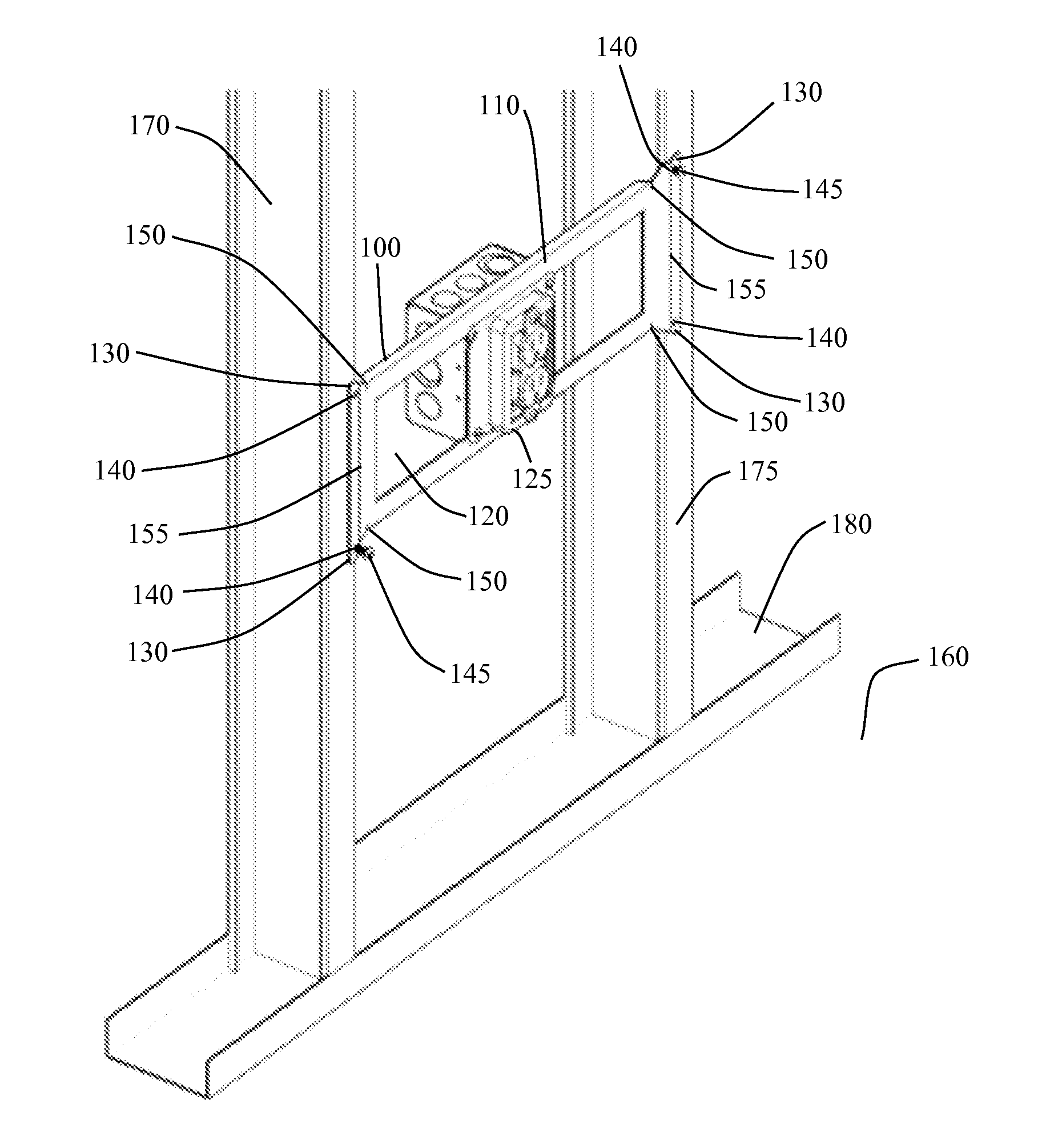
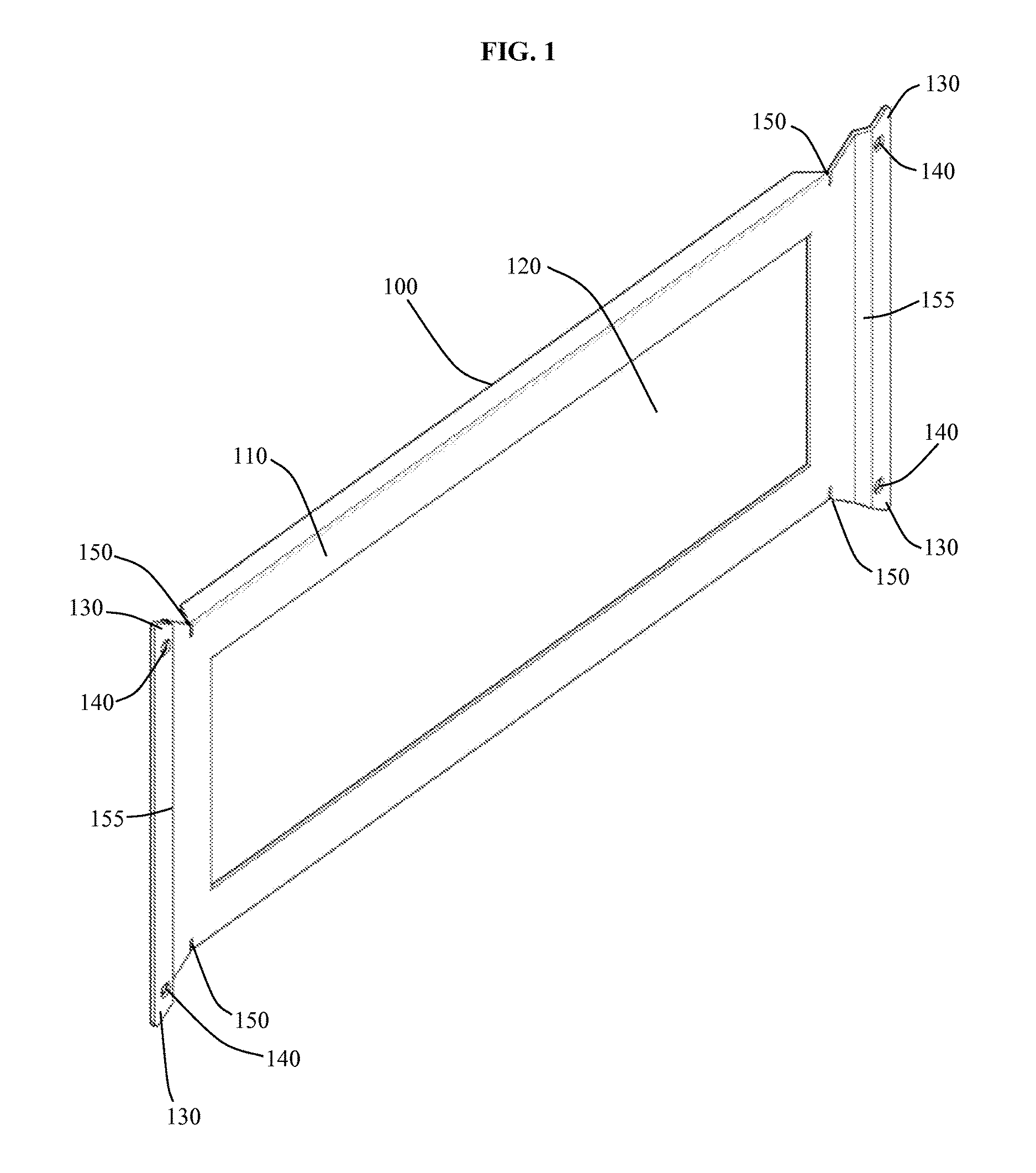
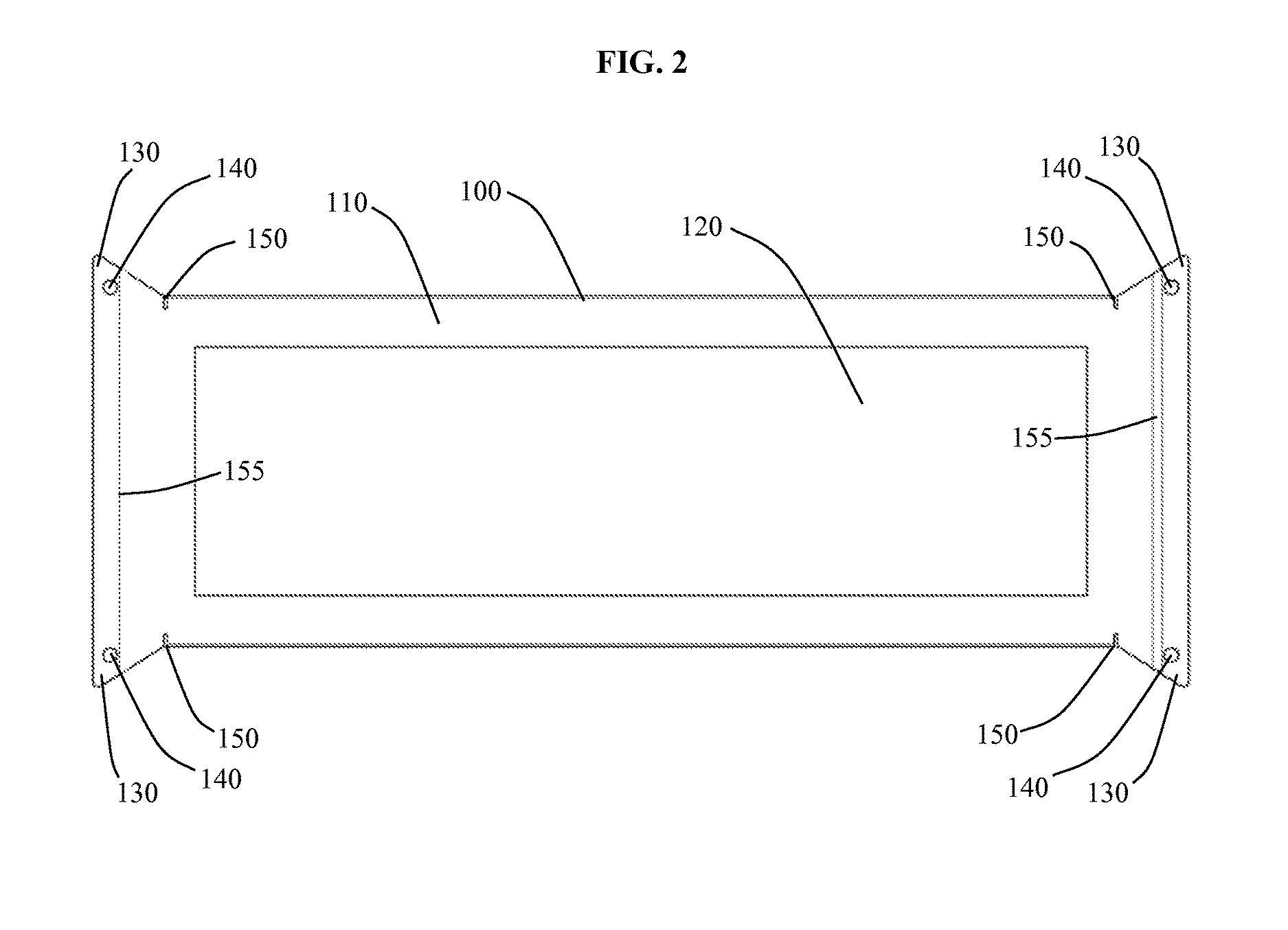
[0035]For the purpose of illustration, the present invention is shown in the most preferred embodiment of a wall bracket for mounting an electrical outlet at a specified height between two wall studs in which the bracket itself is precisely dimensioned so that it can be used to determine the proper mounting height of the electrical box. Methods of using the wall bracket are also illustrated. These embodiments are not intended to limit the scope of the present invention.

[0036]The Self-Measuring Wall Box Bracket invention was developed in part to allow for rapid installation of an electrical outlet between adjacent wall studs, which are set apart at a specified distance defined by standard building codes, and at a specified height, which is defined by standard building and electrical codes, while keeping the cost of materials low. Referring now to the most preferred embodiment of the invention, in FIG. 1, FIG. 2, FIG. 3, FIG. 4, FIG. 5, FIG. 6, FIG. 7, FIG. 8, FIG. 9, FIG. 10, FIG. 11...


PUM


Abstract

Disclosed herein is an apparatus and method for the installation of an electrical outlet between studs at a specified height. The apparatus comprises a body frame with an outlet box mounting frame and ears that extend outwardly from each corner. Each ear has a screw hole, which is precisely positioned, so that the bracket can be used to measure and install an electrical outlet at a specified height. During installation, the bracket is turned sideways, set on the floor and aligned with a wall stud. Next, a screw is secured in the uppermost ear that overlaps the wall stud. Next, the bracket is swung upward until the ears on the opposite side overlap the second wall stud. Next, screws are added to the remaining screw holes and all screws are tightly affixed, so that the apparatus is firmly mounted between the two wall studs at a specified height.

Description

CROSS-REFERENCE TO RELATED APPLICATIONS[0001]Not ApplicableSTATEMENT REGARDING FEDERALLY SPONSORED RESEARCH OR DEVELOPMENT[0002]Not ApplicableREFERENCE TO SEQUENCE LISTING, A TABLE, OR A COMPUTER PROGRAM LISTING COMPACT DISK APPENDIX[0003]Not ApplicableBACKGROUND OF THE INVENTION[0004]1. Field of the Invention[0005]The present invention is in the technical field of brackets. More particularly, the preferred embodiments of the present invention relate generally to brackets made of a singular construction. More particularly, the preferred embodiments of the present invention relate generally to brackets for supporting electrical outlets. More particularly, the preferred embodiments of the present invention relate generally to brackets that span wall studs. More particularly, the preferred embodiments of the present invention relate generally to wall brackets, which set electrical outlets at specific heights.[0006]2. Description of the Related Art[0007]The broad concept of brackets for...

Claims


Application Information

Patent Timeline
IPC IPC(8): H02G3/12H02G1/00
CPCH02G1/00H02G3/125H02G3/12
Inventor TERWILLEGER, DAVID
Owner TERWILLEGER DAVID
Why Eureka
Try Eureka