
Accelerator Foam Generating Device

a technology of accelerator foam and generating device, which is applied in the direction of bathroom accessories, holders and dispensers, domestic applications, etc., can solve the problems of troubleshooting nightmare, increased potential failure points, and increased water damage, and achieves high flow rate

Inactive Publication Date: 2017-01-19
BLANCHAT GREG A
View PDF1 Cites 5 Cited by
  • Summary
  • Abstract
  • Description
  • Claims
  • Application Information

AI Technical Summary

Benefits of technology

The invention described in this patent allows for a complete cleaning system to be installed in a consistent and high-flow rate. It can deliver maximum flows of plain water or water / soap concentrate even when the air supply and soap injection system are deactivated.

Problems solved by technology

This water damage may end up being more severe than the damage caused solely by the fire.
This has been a problem for many CAFS manufacturers because they have incorporated balancing valves, pressure regulators and manual adjustments or other electronics to achieve the precise pressures for mixing.
Relying on these types of components or human interaction with the system to make it work correctly, introduces more potential failure points and creates a troubleshooting nightmare.
Often times, CAFS, due to the complex plumbing and components or flow restrictions, are not capable of flowing plain water without air injection for scenarios where it is preferred to use water or water / soap concentrate only.
For these reasons, CAFS has gained a bad reputation in firefighting for being extremely unreliable, not user-friendly and expensive.

Method used


Image

  • Accelerator Foam Generating Device
  • Accelerator Foam Generating Device
  • Accelerator Foam Generating Device

Examples


Embodiment Construction

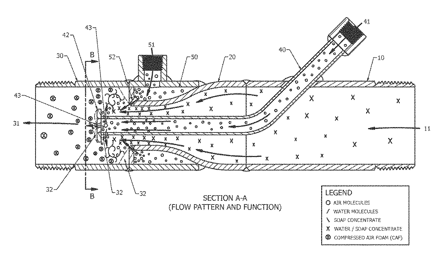
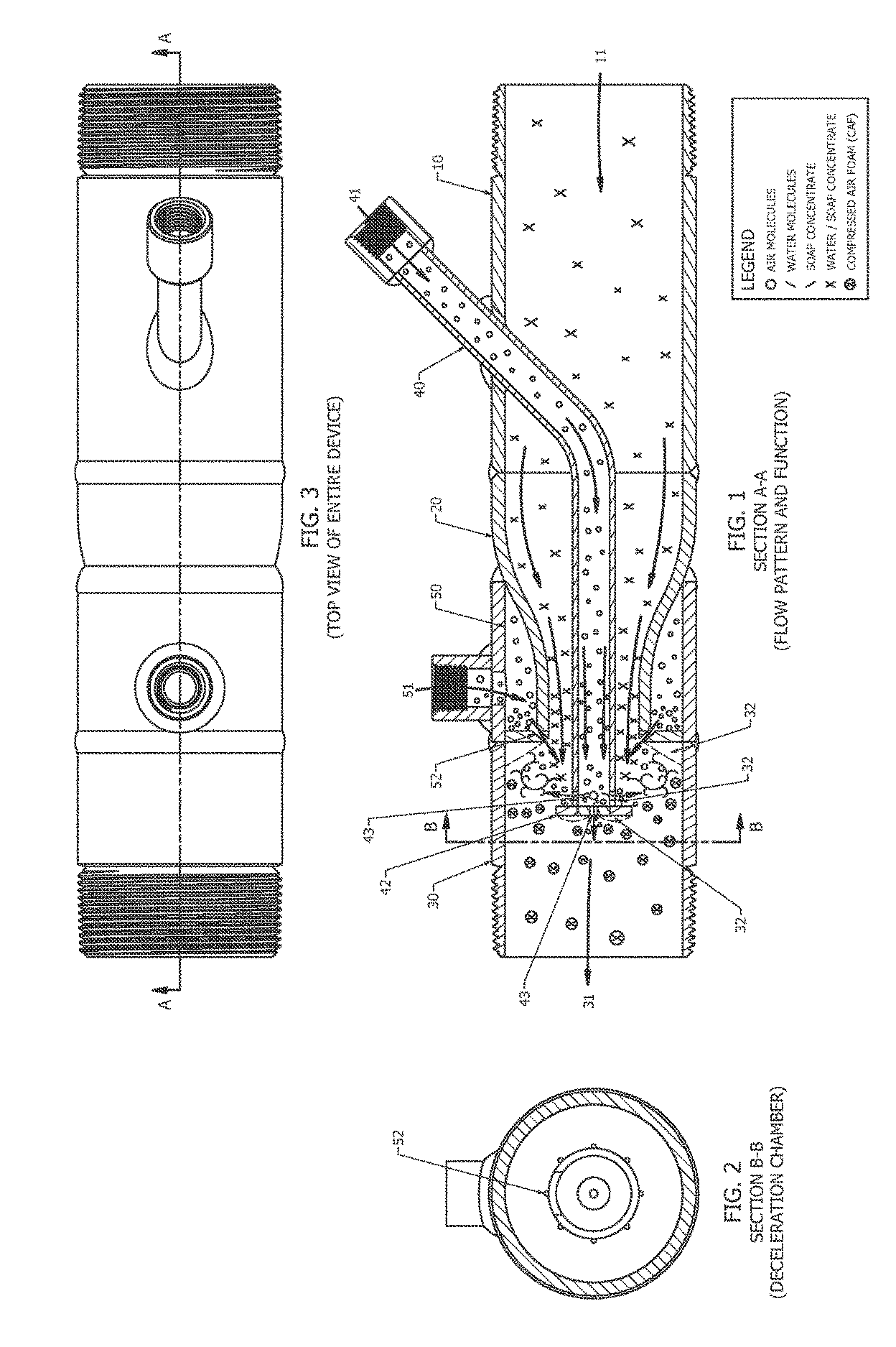
[0001]The present mixing device has three primary chambers—the water / soap concentrate entry chamber 10, acceleration chamber 20 and deceleration chamber 30. These chambers, shown in FIG. 1, are assembled together in this respective order. In addition, an air manifold 50 is wrapped around the acceleration chamber 20 and an air diffuser tube 40 is assembled inside the center of the acceleration chamber 20. These chambers are preferably welded together for strength and leak protection but may be connected by other means. They are preferably built from stainless steel for durability and corrosion resistance but alternative materials with or without coatings which achieve similar strength and corrosion resistance can be used. Such materials could include brass and high strength plastics.

[0002]The entry chamber 10 and deceleration chamber 30 are preferably sized such that their inlet and outlet, respectively, is sized to accommodate the size of piping used in the particular firefighting a...


PUM


Abstract

An air and water / soap concentrate mixing device which creates high quality compressed air foam without restricting the flow of liquid through the apparatus. The device consists of three water / soap concentrate chambers, an air manifold and a central air diffuser tube. Water / soap concentrate flow is increased through the device from the entry chamber (first) thru the acceleration (second) chambers. Upon entering the deceleration (third) chamber, the water / soap concentrate perimeter is laced with pressurized air from the air manifold wrapping the acceleration chamber. At the same time, pressurized air is also diffused and embedded in the center of the water / soap concentrate flow via the air diffuser tube. As the accelerated water / soap concentrate enters the deceleration chamber, the flow is dramatically decreased. This slowing of the water / soap concentrate and the introduction of pressurized air causes a pressure volatility and turbulence inside the deceleration chamber allowing the pressures of the water / soap concentrate and air to equalize and mix creating foam bubbles. The device is also capable of flowing plain water or water / soap concentrate through the device if the pressurized air system or soap injection system is deactivated.

Description

DETAILED DESCRIPTION OF THE INVENTION[0001]The present mixing device has three primary chambers—the water / soap concentrate entry chamber 10, acceleration chamber 20 and deceleration chamber 30. These chambers, shown in FIG. 1, are assembled together in this respective order. In addition, an air manifold 50 is wrapped around the acceleration chamber 20 and an air diffuser tube 40 is assembled inside the center of the acceleration chamber 20. These chambers are preferably welded together for strength and leak protection but may be connected by other means. They are preferably built from stainless steel for durability and corrosion resistance but alternative materials with or without coatings which achieve similar strength and corrosion resistance can be used. Such materials could include brass and high strength plastics.[0002]The entry chamber 10 and deceleration chamber 30 are preferably sized such that their inlet and outlet, respectively, is sized to accommodate the size of piping ...

Claims


Application Information

Patent Timeline
Patent Type & Authority Applications(United States)
IPC IPC(8): A47K5/14B05B7/00
CPCB05B7/0025A47K5/14
Inventor BLANCHAT, GREG A.
Owner BLANCHAT GREG A
Learn More