Inkjet head and method of manufacturing inkjet head

a technology of inkjet head and inkjet printing, which is applied in the direction of piezoelectric/electrostrictive transducers, transducer types, printing, etc., can solve the problems of speed distribution, non-uniform production process, and deterioration of image quality

Active Publication Date: 2007-03-29
KONICA MINOLTA INC
View PDF4 Cites 29 Cited by
  • Summary
  • Abstract
  • Description
  • Claims
  • Application Information

AI Technical Summary

Benefits of technology

[0084] The structure of (11) further permits easy adjustment of the shear deformation function of the driving wall through the opening from the rear surface of the head chip, even when a wiring substrate for wire connection is provided on the rear surface of the head chip.
[0085] The structure of (12) further permits exposition of all channels and easy adjustment of the shear deformation function of the driving wall from the rear surface of the head chip, even when a wiring substrate for wire connection is provided on the rear surface of the head chip.
[0086] The structure of (13) further permits easy adjustment of the shear deformation function of the driving wall by laser.
[0087] The structure of (14) further permits easy mechanical adjustment of the shear deformation function of the driving wall.
[0088] The structure of (15) further permits easy adjustment of the shear deformation function of the driving wall by laser heating.

Problems solved by technology

In both types, nonuniform channel characteristics cause dispersion of landing accuracy of ink due to nonuniform speed distribution, thus deteriorates the quality of obtained image.
Inkjet head in practice usually has some speed distribution because of dispersion of performance of PZT as a material and of non-uniformity of production process.
To make speed distribution uniform, there is a method to optimize driving voltage for each channel, however since a driving circuit has to be provided for each channel, cost increase is a problem.
Usually, because a single power source applies voltage to each channel, each driving voltage becomes the same and it is unavoidable that speed of ink jetted from each nozzle varies.
In such harmonica type head chip, connection of a wiring to apply driving voltage to the driving electrode is difficult.
Thus, it is difficult to adjust the driving electrode by trimming after manufacturing the inkjet head because the substrate obstructs adjustment.
However, bending status has to be kept during trimming work and it is not preferable since there are risks of folding down, separation and breakage of the substrate.

Method used


Image

  • Inkjet head and method of manufacturing inkjet head
  • Inkjet head and method of manufacturing inkjet head
  • Inkjet head and method of manufacturing inkjet head

Examples


Embodiment Construction

[0103] The following describes the embodiments of the present invention with reference to drawings:

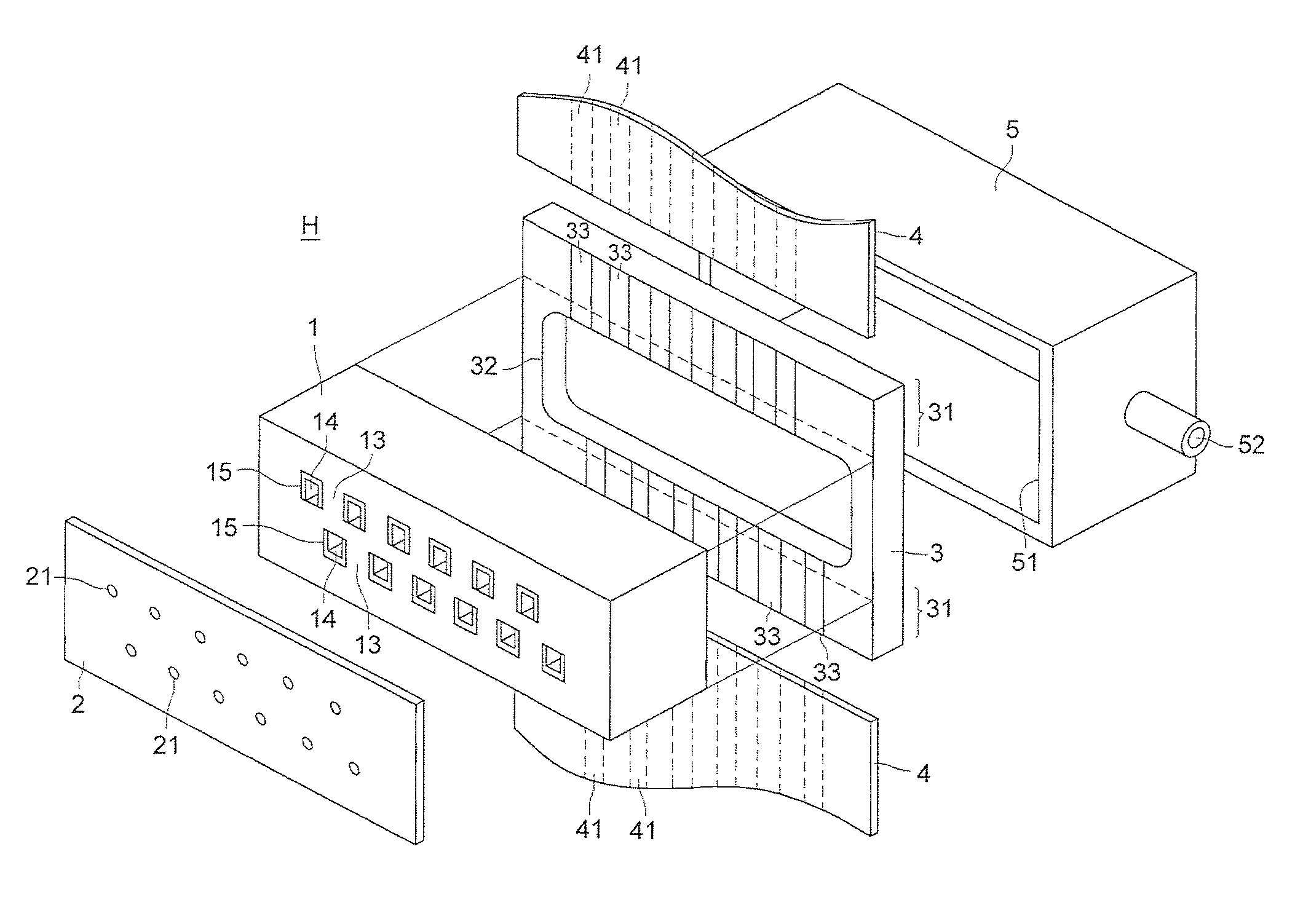
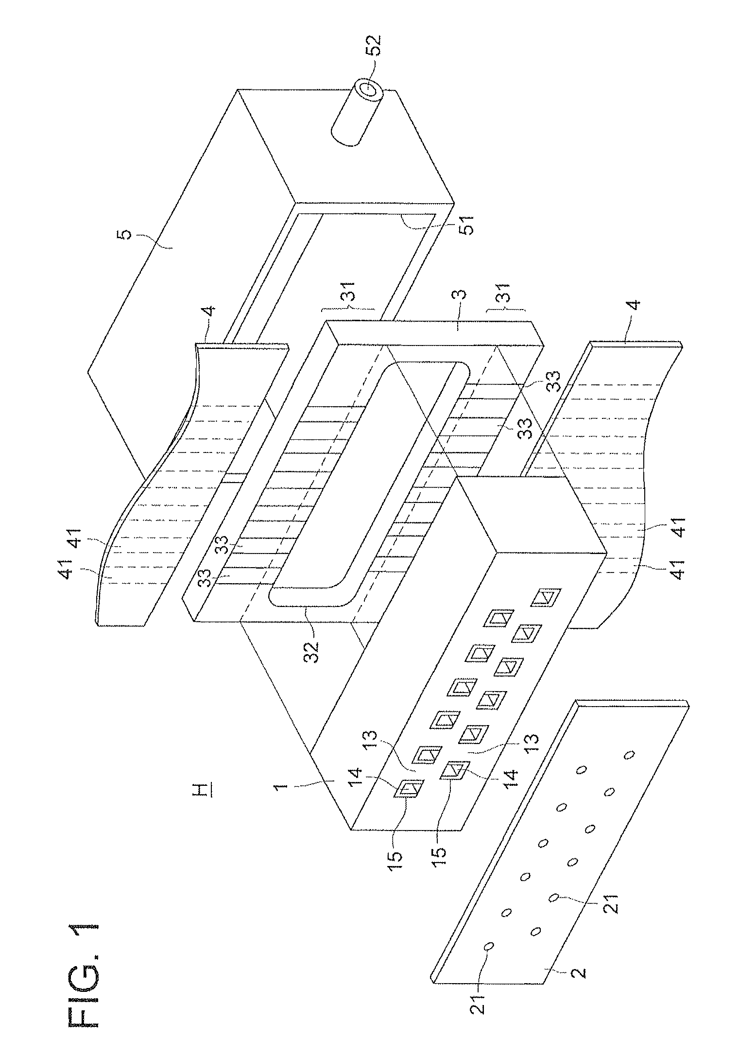
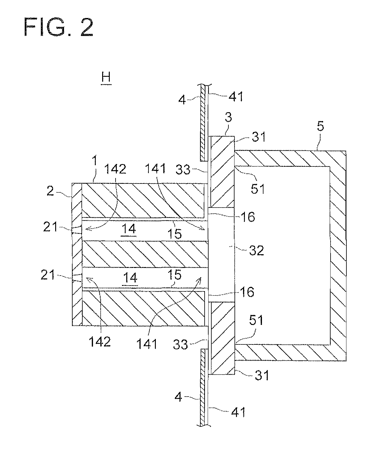
[0104]FIG. 1 is an exposed perspective view showing an example of the inkjet head of the present invention. FIG. 2 is a cross sectional view, wherein H denotes an inkjet head, numeral 1 is a head chip, numeral 2 is a nozzle plate connected to the front surface of the head chip 1, numeral 3 is a wiring substrate connected to the rear surface of head chip 1, numeral 4 is an FPC connected to the wiring substrate 3, and numeral 5 is an ink manifold connected to the rear surface of the wiring substrate 3.

[0105] In the present specification, the surface where ink is jetted from the head chip 1 is defined as a “front surface”, and the opposite side thereof is defined as “rear surface”. When head chip 1 is viewed from the front surface or rear surface, the outer surfaces on the top and bottom with the channel arranged in parallel are called “top surface” and “bottom surface”, respectively.

[...


PUM

PropertyMeasurementUnit
thicknessaaaaaaaaaa
drive frequencyaaaaaaaaaa
depthaaaaaaaaaa

Abstract

An inkjet head including: a head chip having; driving walls composed of piezoelectric element, wherein shear deformation is caused by applying voltage so as to jet ink, channels arranged alongside the driving walls alternatively to contain ink, outlet and inlet ports respectively provided on a front and rear surface of the head chip for each channel, driving electrodes formed on surfaces of the driving walls to apply voltage to the driving walls, and connection electrodes formed on the rear surface of the head chip to connect the driving electrodes electrically; a wiring substrate, wherein wiring electrodes are formed to apply voltage to the driving electrode through the connection electrode, bonded on the rear surface of the head chip to protrude from the head chip in a direction perpendicular to a direction of a channel array so that all the channels are exposed at the rear surface of the head chip.

Description

[0001] This application is based on Japanese Patent Application Nos. 2005-2417 filed on Aug. 23, 2005 and 2006-165378 filed on Jun. 14, 2006 in Japanese Patent Office, the entire content of which is hereby incorporated by reference. BACKGROUND OF THE INVENTION [0002] The present invention relates to an inkjet head and to a method of manufacturing the inkjet head, and in particular to an inkjet head wherein speed distribution of each channel is easily uniformed even incase of a harmonica type head chip, and to a method of manufacturing the inkjet head thereof. [0003] In recent years, in inkjet heads to record images by jetting ink from a nozzle, multi channel has been developed to improve recording speed and image quality. In such multi channel inkjet head, uniformity of speed distribution of ink jetted from the nozzles is an important factor. Since jetting speed of ink from the nozzle is related to a volume of ink particle and a diameter of ink particle, the channel characteristics ...

Claims


Application Information

Patent Timeline
Patent Type & Authority Applications(United States)
IPC IPC(8): B41J2/05
CPCB41J2/14209Y10T29/49401B41J2/1623B41J2/1632B41J2/1634B41J2/1642B41J2/1643B41J2/1646B41J2002/14362B41J2002/14491B41J2/04501Y10T29/42Y10T29/49128Y10T29/49147B41J2/1609
Inventor WATANABE, HIDEO
Owner KONICA MINOLTA INC
Why Eureka
Try Eureka