Stereoscopic display device and method for manufacturing the same

a display device and stereoscopic technology, applied in the field of display, can solve problems such as unsuitability for public places, and achieve the effect of reducing the phenomenon of moire fringe during display and reducing the moire fring

Active Publication Date: 2017-01-19
BOE TECH GRP CO LTD
View PDF0 Cites 11 Cited by
  • Summary
  • Abstract
  • Description
  • Claims
  • Application Information

AI Technical Summary

Benefits of technology

[0006]The embodiments of the present invention provide a stereoscopic display device and a method for manufacturing the same, which can reduce Moire fringe phenomenon during displaying of a naked eye 3D display device.
[0010]the grating comprises a plurality of optical structures arranged parallel to each other; a preset angle β is arranged between the optical structure and an X direction of the display panel, thereby reducing Moire fringe phenomenon during displaying.
[0036]the grating comprises a plurality of optical structures arranged parallel to each other; a preset angle β is arranged between the optical structure and an X direction of the display panel, thereby reducing Moire fringe phenomenon during displaying.
[0061]the grating comprises a plurality of optical structures arranged parallel to each other; a preset angle β is arranged between the optical structure and an X direction of the display panel, thereby reducing Moire fringe phenomenon during displaying. In particular, in one aspect, to realize stereoscopic displaying, the display panel comprises a plurality of first display units for displaying left eye images and a plurality of second display units for displaying right eye images. The plurality of first display units and the plurality of second display units are arranged alternately in a vertical direction of the display panel, therefore the left eye images and the right eye images can be separated with the effect of the grating. Each first display unit and each second display unit respectively comprises m sub pixels arranged in the Y direction. T is a sub pixels number of a layout position difference in the Y direction between two first display units respectively positioned in two adjacent columns, or a sub pixels number of a layout position difference in the Y direction between two second display units respectively positioned in two adjacent columns, T being a positive integer of 1˜100. Moreover, to reduce Moire fringe, the grating comprises a plurality of optical structures arranged parallel to each other; a preset angle β is arranged between the optical structure and an X direction of the display panel; 0.8θ≦β≦1.2θ; andθ=arctan[(Tm+12×m)Pixel].The preset angle β can be determined with T, therefore the probability of forming Moire fringes is reduced, which Moire fringes are formed by interference between light passing through the grating with the preset angle and light passing through the black matrix. In another aspect, a size of the sub pixel in the Y direction is smaller than a size of the sub pixel in the X direction, therefore the display device is a vertical screen display device. To sum up, for a vertical screen display device, when viewed in a horizontal direction, with the layout position in the embodiments of the present invention, 3D displaying with separated left eye images and right eye images can be realized; moreover, a slant angle for reducing Moire fringes can also be determined, thereby reducing Moire fringe phenomenon during displaying of a naked eye 3D display device.

Problems solved by technology

Traditional stereoscopic display device requires the viewer wearing assistant tools such as polarized glasses, complementary colors glasses or LCD shutter glasses; though it has a good stereoscopic effect, it is not suit for public places, especially the advertising display and so on.

Method used


Image

  • Stereoscopic display device and method for manufacturing the same
  • Stereoscopic display device and method for manufacturing the same
  • Stereoscopic display device and method for manufacturing the same

Examples


embodiment 1

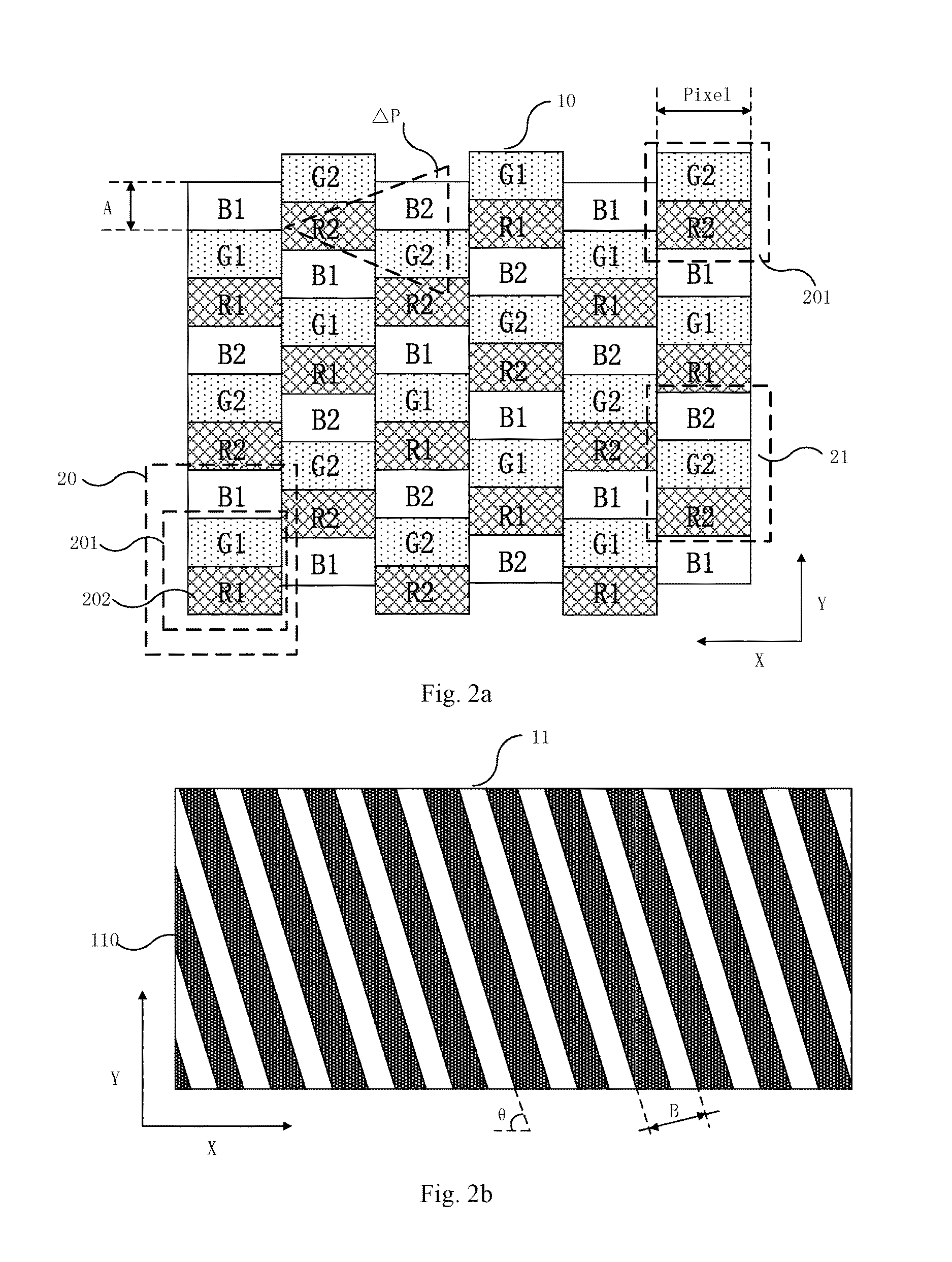
[0108]To eliminate Moire fringes formed between the diagonal dark state (a-c) of the black matrix 12 and the grating 11, θ between the grating 11 and the X direction of the display panel 10 should meet the formula:

α-θ>arccosP2[n2(A3×sinα)2+B2]-(A2×sinα)2B22n(A3×sinα)BP2;(2)

[0109]wherein α is an angle between a diagonal of the sub pixel 202 and the Y direction.

[0110]In particular, as shown in FIG. 4b, when one sub pixel 202 is formed as one square, the diagonal of the sub pixel 202 is the diagonal of the square; an angle α of 45° is formed between the diagonal and the Y direction.

[0111]For another example, as shown in FIG. 4a, when two sub pixels 202 are formed as one square, an angle

α=arctanPixelPixel / 2=arctan2=63.43°

is formed between the diagonal of the sub pixel 202 and the Y direction.

[0112]Similarly, when three sub pixels 202 are formed as one square, an angle

α=arctanPixelPixel / 3=arctan3=71.56°

is formed between the diagonal of the sub pixel 202 and the Y direction.

[0113]Other...

embodiment 2

[0122]To eliminate Moire fringes formed between the horizontal dark state (a-b) of the black matrix 12 and the grating 11, θ between the grating 11 and the X direction of the display panel 10 should meet the formula:

θ>arccosP2(n2A2+B2)-A2B22nABP2;(3)

[0123]wherein the sampling process for the Moire fringes is shown in FIG. 7. There are multiple intersection points (indicated with dots) between the horizontal dark state (a-b) of the black matrix 12 and the grating 11. Several (0, 1, 2, 3 . . . ) sampling points are selected from these intersection points to sample the Moire fringes. There is a Moire fringe with a certain width between each sampling point and a fixed point d (an intersection point adjacent to the sampling point).

[0124]For example, when the sampling number n=1, the Moire fringe formed between the fixed point d and the sampling point 0 can be sampled, obtaining a Moire fringe with a width W1 between the fixed point d and the sampling point 0; when the sampling number ...

embodiment 3

[0126]To eliminate Moire fringes formed between the vertical dark state (b-c) of the black matrix 12 and the grating 11, θ between the grating 11 and the X direction of the display panel 10 should meet the formula:

θ<90°-arccosP2(n2A2 / 9+B2)-A2B2 / 92nABP2 / 3;(4)

[0127]wherein the sampling process for the Moire fringes is shown in FIG. 7. There are multiple intersection points (indicated with dots) between the vertical dark state (b-c) of the black matrix 12 and the grating 11. Several (0, 1, 2, 3 . . . ) sampling points are selected from these intersection points to sample the Moire fringes. There is a Moire fringe with a certain width between each sampling point and a fixed point d (an intersection point adjacent to the sampling point).

[0128]For example, when the sampling number n=1, the Moire fringe formed between the fixed point d and the sampling point 0 can be sampled, obtaining a Moire fringe with a width W1 between the fixed point d and the sampling point 0; when the sampling n...


PUM

PropertyMeasurementUnit
angleaaaaaaaaaa
widthaaaaaaaaaa
sizeaaaaaaaaaa

Abstract

The embodiments of the present invention provide a stereoscopic display device and a method for manufacturing the same, relating to the technical field of display; the stereoscopic display device and the method for manufacturing the same can reduce Moire fringe phenomenon during displaying of a naked eye 3D display device. The stereoscopic display device comprises a display panel and a grating, wherein the display panel comprises a plurality of first display units and a plurality of second display units, the plurality of first display units and the plurality of second display units are arranged alternately in a Y direction of the display panel; the grating comprises a plurality of optical structures arranged parallel to each other; a preset angle β is arranged between the optical structure and an X direction of the display panel, thereby reducing Moire fringe phenomenon during displaying.

Description

FIELD OF THE INVENTION[0001]The present invention relates to the technical field of display, in particular to a stereoscopic display device and a method for manufacturing the same.BACKGROUND OF THE INVENTION[0002]Stereoscopic display device has characteristics of large amount of information, being capable of reproducing all the three-dimensional information of an actual scene, so that a viewer can see the distance and depth of each object in an image from the display device directly, thus the viewer can obtain more overall and intuitive information. Therefore, with the rapid development of the stereoscopic display technology, there is also a growing demand for stereoscopic display device. Traditional stereoscopic display device requires the viewer wearing assistant tools such as polarized glasses, complementary colors glasses or LCD shutter glasses; though it has a good stereoscopic effect, it is not suit for public places, especially the advertising display and so on. Therefore, th...

Claims


Application Information

Patent Timeline
Patent Type & Authority Applications(United States)
IPC IPC(8): G02B27/22G02B27/00H04N13/04G02F1/1343G02F1/1335G02B30/27G02B30/32
CPCG02B27/2214G02F1/134309G02F1/133512H04N13/0422H04N2213/001G02B27/0025G02F2001/134345G02F2201/52H04N13/0404G02B30/27G02B30/32H04N13/305H04N13/324H04N13/31H04N13/317
Inventor WEI, WEI
Owner BOE TECH GRP CO LTD
Why Eureka
Try Eureka