
Stereo display device

A technology of a stereoscopic display device and a central axis, which is applied in the directions of optical elements, optics, instruments, etc., can solve the problems of uneven light pattern, affecting the imaging quality of the stereoscopic display device, etc., so as to improve the imaging quality, reduce the moire effect, Avoid resolution reduction effects

Inactive Publication Date: 2015-03-18
DAYU OPTOELECTRONICS
View PDF6 Cites 13 Cited by
  • Summary
  • Abstract
  • Description
  • Claims
  • Application Information

AI Technical Summary

Problems solved by technology

However, since the size of the periodic structure of the display panel and the pixel array is relatively close, it is easy for the light emitted from the display panel to present uneven light patterns after passing through the lenticular lens array, so that the viewer is easy to see the fixed interval when viewing the stereoscopic image. The change of the light and dark lines of the light and dark lines produces the so-called moire effect (Moiré Effect), which seriously affects the image quality of the stereoscopic display device.

Method used


Image

  • Stereo display device
  • Stereo display device
  • Stereo display device

Examples


Embodiment Construction

[0014] In order to make the above-mentioned features and advantages of the present invention more comprehensible, the following specific embodiments are described in detail together with the accompanying drawings.

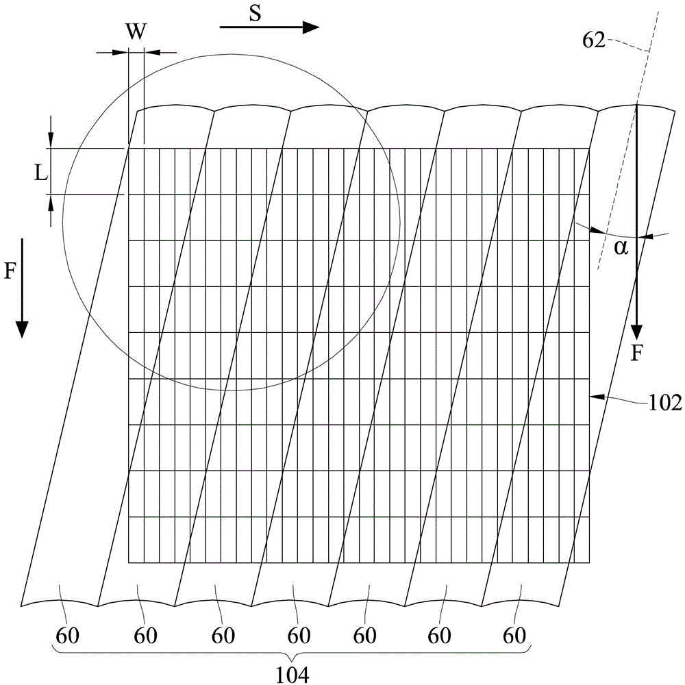
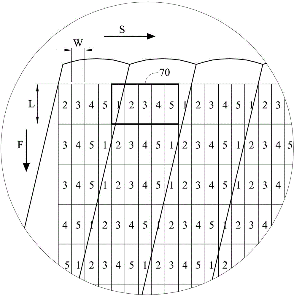
[0015] Please refer to figure 1 and figure 2 , which are respectively a schematic top view of an embodiment of the stereoscopic display device disclosed in the present invention and the basis figure 1 The partial enlarged schematic diagram of the stereoscopic display device. The stereoscopic display device includes a pixel array 102 and a lens array 104 . The pixel array 102 includes a plurality of sub-pixels (ie figure 1 and figure 2 the rectangle in ). In this embodiment, the pixel array 102 may include 315 sub-pixels, each column may have 35 sub-pixels (that is, thirty-five sub-pixels arranged along the second direction S), each row may have 9 sub-pixels For a pixel (that is, nine sub-pixels arranged along the first direction F), the first direction F an...


PUM


Abstract

The invention discloses a stereo display device. The stereo display device comprises a first pixel array and a lens array, wherein the pixel array comprises a plurality of sub pixels; the lens array comprises a plurality of columnar lenses in parallel arrangement, wherein each columnar lens comprises a central shaft which is oblique corresponding to the first direction and forms an oblique angle with the first direction; the lens array is used for receiving and transmitting light rays emitted by the sub pixels, and P viewpoints are formed at one viewpoint end; the sub pixels for forming each viewpoint are arranged corresponding to the central shaft, wherein P>=2 and P is an integer. The stereo display device can be used for reducing the Moire effect generated because the cycle structures of the lens array and the pixel array are relatively approximate.

Description

technical field [0001] The invention relates to a display device, in particular to a stereoscopic display device. Background technique [0002] At present, there are mainly two methods for stereoscopic display devices to display stereoscopic images. One is that the viewer must wear special glasses to watch the display device, so that the images received by the left eye and the right eye are different, or the images received by the left eye and the right eye are different. Three-dimensional images are produced by alternating eye images. This method requires the viewer to wear additional glasses to see the three-dimensional images, which is inconvenient to use. [0003] The other is a naked-eye display device. This method is to use the grating principle for the display device, so that the viewer does not need to wear any additional devices to make the images seen by the left eye and the right eye different and generate a three-dimensional image. It is currently used in printe...

Claims


Application Information

Patent Timeline
Patent Type & Authority Applications(China)
IPC IPC(8): G02B27/22
CPCG02B30/27G02B30/50
Inventor 刘得杏朱宥铭陈宇杰
Owner DAYU OPTOELECTRONICS
Learn More