Light redirecting film having varying optical elements

a technology of optical elements and light redirecting films, applied in lighting devices, lighting and heating apparatuses, instruments, etc., can solve the problems of reducing the brightness of the axis, the inability to adequately solve the moiré problem, and the inability to achieve the effect of reducing the moiré pattern, avoiding objectionable visual artifacts, and high quality requirements

Inactive Publication Date: 2010-01-05
SKC HI TECH & MARKETING CO LTD CO REGISTRATION NO 161511 0225312
View PDF10 Cites 11 Cited by
  • Summary
  • Abstract
  • Description
  • Claims
  • Application Information

AI Technical Summary

Benefits of technology

[0013]Embodiments of the invention provide light redirecting films that reduce Moiré, mask cosmetic defects, provide high on-axis gain, and avoid objectionable visual artifacts when used in a liquid crystal display.

Problems solved by technology

Previous light redirecting films suffer from visible Moiré patterns when the light redirecting film is used with a liquid crystal or other display.
The surface elements of the light redirecting film interact with other optical films, the pattern of printed dots or three-dimensional elements on the back of the light guide plate, or the pixel pattern inside the liquid crystal modulator to create Moiré, an undesirable effect.
The above techniques to reduce Moiré also cause a decrease in on-axis brightness or do not work to adequately solve the Moiré problem.
Previous light redirecting films also suffer from high quality requirements and production costs.
Very small defects in linear arrays of prisms, stray contamination particles, and small scratches can be visible in the film and assembled display.
In addition, defects on lower layers of the display assembly are often visible through the light redirecting film.
As a result the films suffer from high reject rates and low yield, or they must be manufactured to exacting standards, in clean rooms, and with great care in handling during fabrication and assembly into displays.
The above techniques increase cost, cause a decrease in on-axis brightness, or do not adequately hide defects.
However, light redirecting films with varying individual optical elements can have unexpected problems that can be difficult to solve, including loss of gain, varying gain, cosmetic defects, and visually objectionable patterns.

Method used


Image

  • Light redirecting film having varying optical elements
  • Light redirecting film having varying optical elements
  • Light redirecting film having varying optical elements

Examples


Embodiment Construction

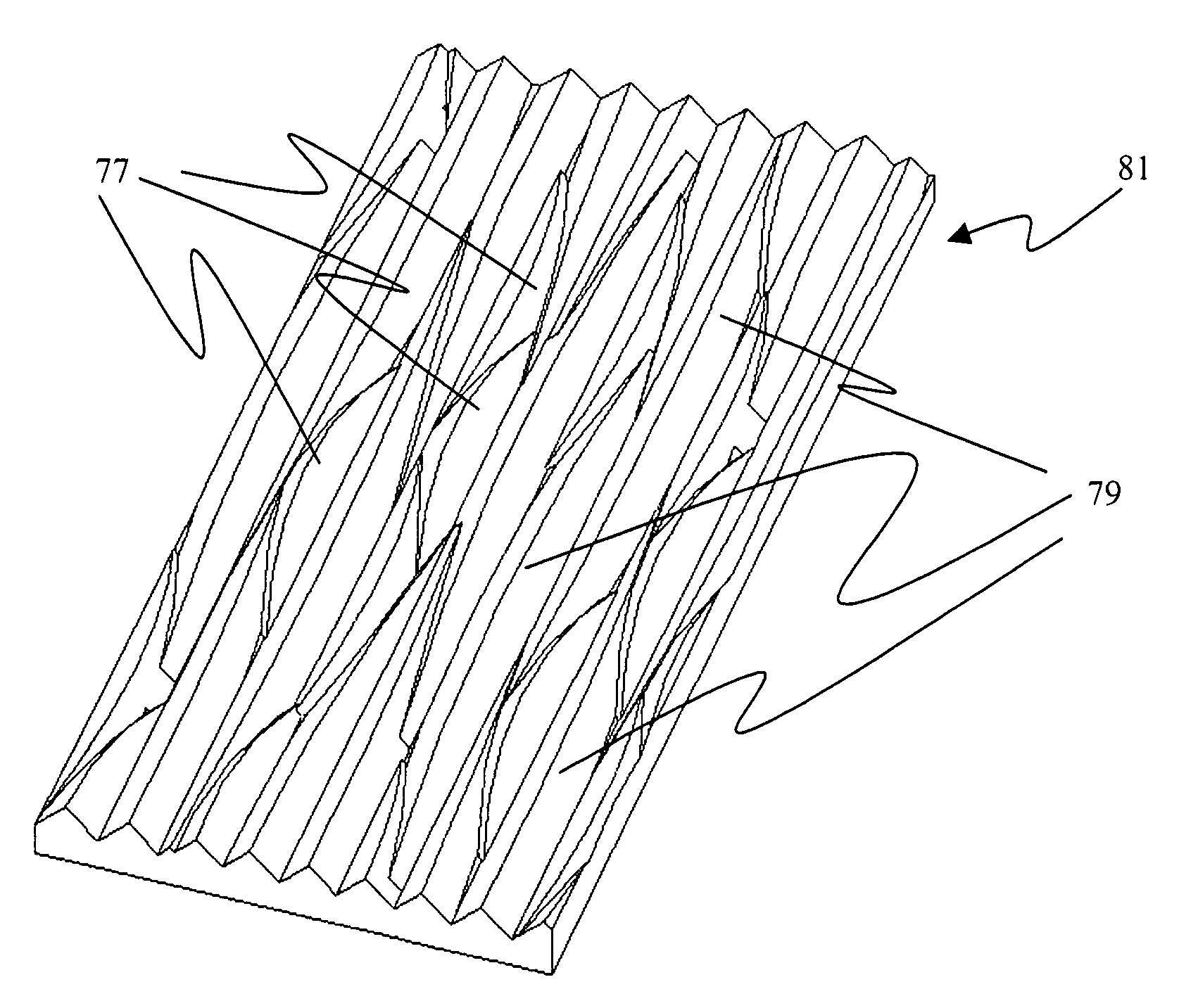
[0034]Embodiments of the invention have numerous advantages compared to current light redirecting films. Two or more size and shape distributions of optical elements and their placement on the film produce high on-axis gain while significantly reducing Moiré. The light redirecting film of the invention has a diffuse or textured look and avoids objectionable patterns. The multiple shapes of optical elements mask cosmetic defects in and under the light redirecting film. A minor portion of optical elements extending above the rest of the elements provide space between the film and contacting surfaces, to avoid optical coupling at the ridges of most elements, avoid Newton rings, and protect the ridges of most elements from damage. The film of the invention provides a higher on-axis gain with multiple sized elements than a light redirecting film with only one sized element. These and other advantages will be apparent from the detailed description below.

[0035]Individual optical elements, ...


PUM


Abstract

The invention relates to a light redirecting film comprising a thin optically transparent substrate having opposite sides, one side of the substrate substantially covered by elongated individual optical elements whose longest dimensions are substantially aligned in a lengthwise direction, wherein the shape of at least some of the optical elements have a visually significant difference, and wherein the layout of optical element shapes and locations is such that objectionable patterns are not visible in the film under standard LCD backlight viewing conditions.

Description

FIELD OF THE INVENTION[0001]The present invention relates generally to a light redirecting film for inclusion in an optical display assembly. More particularly the invention relates to light redirecting films having individual optical elements wherein the layout of optical element shapes and locations is such that objectionable patterns are not visible.BACKGROUND OF THE INVENTION[0002]The use of a variety of light redirecting films in backlit displays is well known. Light redirecting films are typically thin transparent optical films or substrates that redirect the light passing through the films such that the distribution of the light exiting the films is directed more normal to the surface of the films. The output light intensity normal to the film divided by input light intensity normal to the film is called the “on-axis gain” of the film. Typically, light redirecting films are provided with ordered prismatic grooves, lenticular grooves, or pyramids on the light exit surface of t...

Claims


Application Information

Patent Timeline
Patent Type & Authority Patents(United States)
IPC IPC(8): G02B13/10
CPCG02B5/0278G02B6/0053G02F1/133526G02B13/10G02B5/0221G02B5/0231G02F2001/133607G02F1/133607G02B5/0268G02B6/0051
Inventor WILSON, RANDALL H.GUIGUIZIAN, PAUL J.BOURDELAIS, ROBERT P.
Owner SKC HI TECH & MARKETING CO LTD CO REGISTRATION NO 161511 0225312
Why Eureka
Try Eureka