
Bone Securement Apparatus and Method

a bone and securement technology, applied in the direction of osteosynthesis devices, bone plates, fasteners, etc., can solve the problems of complex loadbearing, complex loadbearing which is seen, and the destruction of the articular surface rather quickly

Active Publication Date: 2017-01-26
GRANT WILLIAM P
View PDF1 Cites 39 Cited by
  • Summary
  • Abstract
  • Description
  • Claims
  • Application Information

AI Technical Summary

Benefits of technology

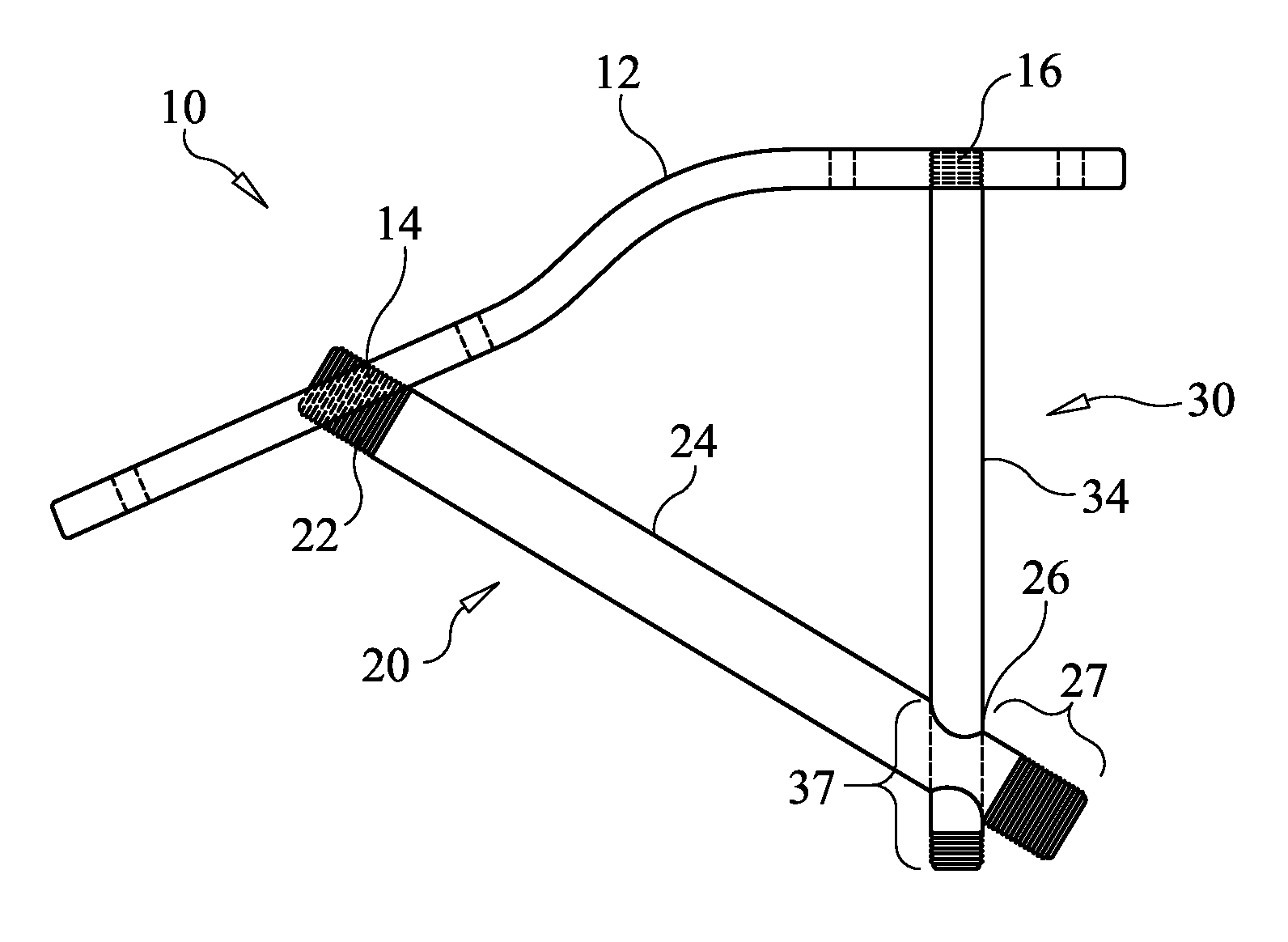
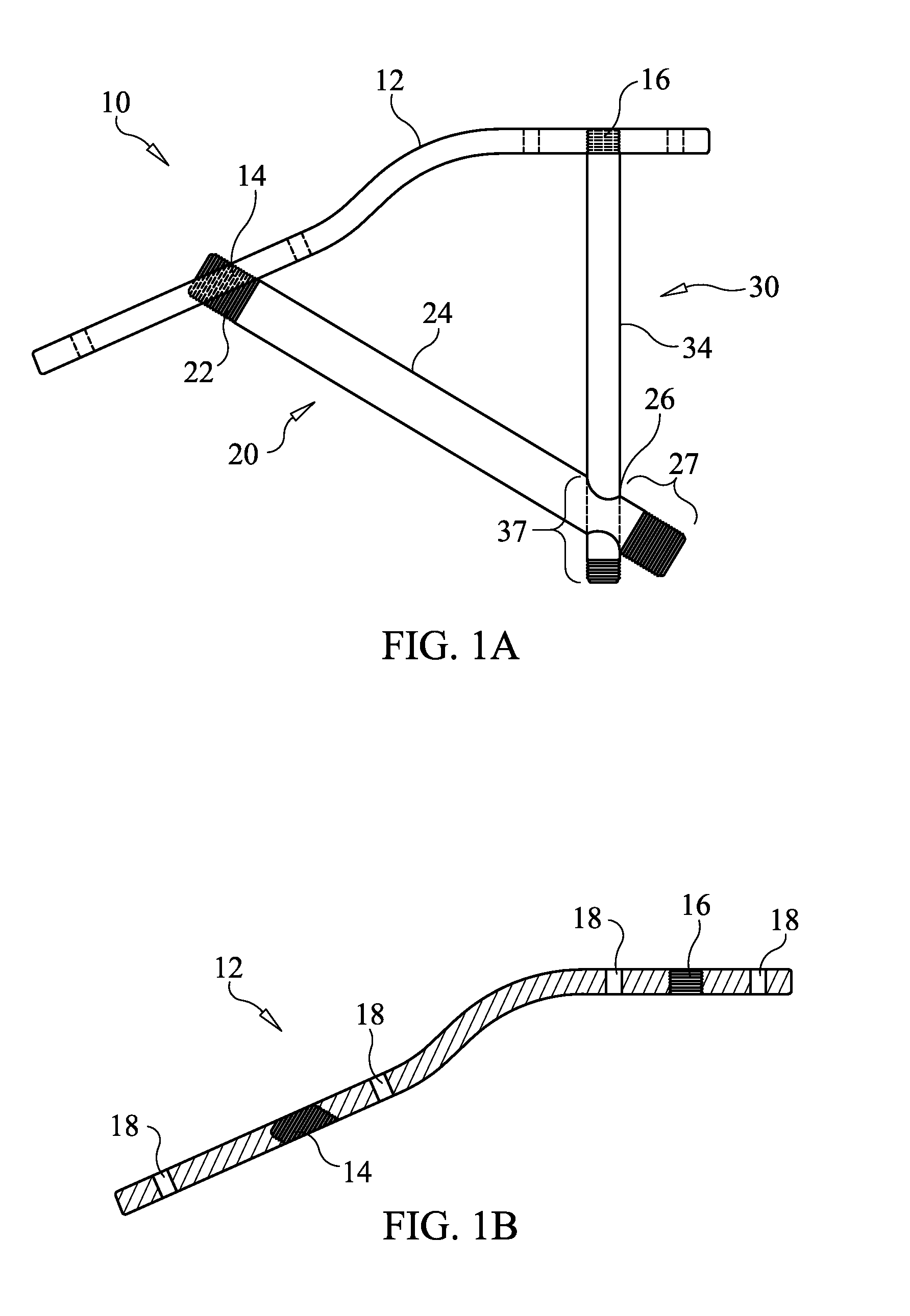
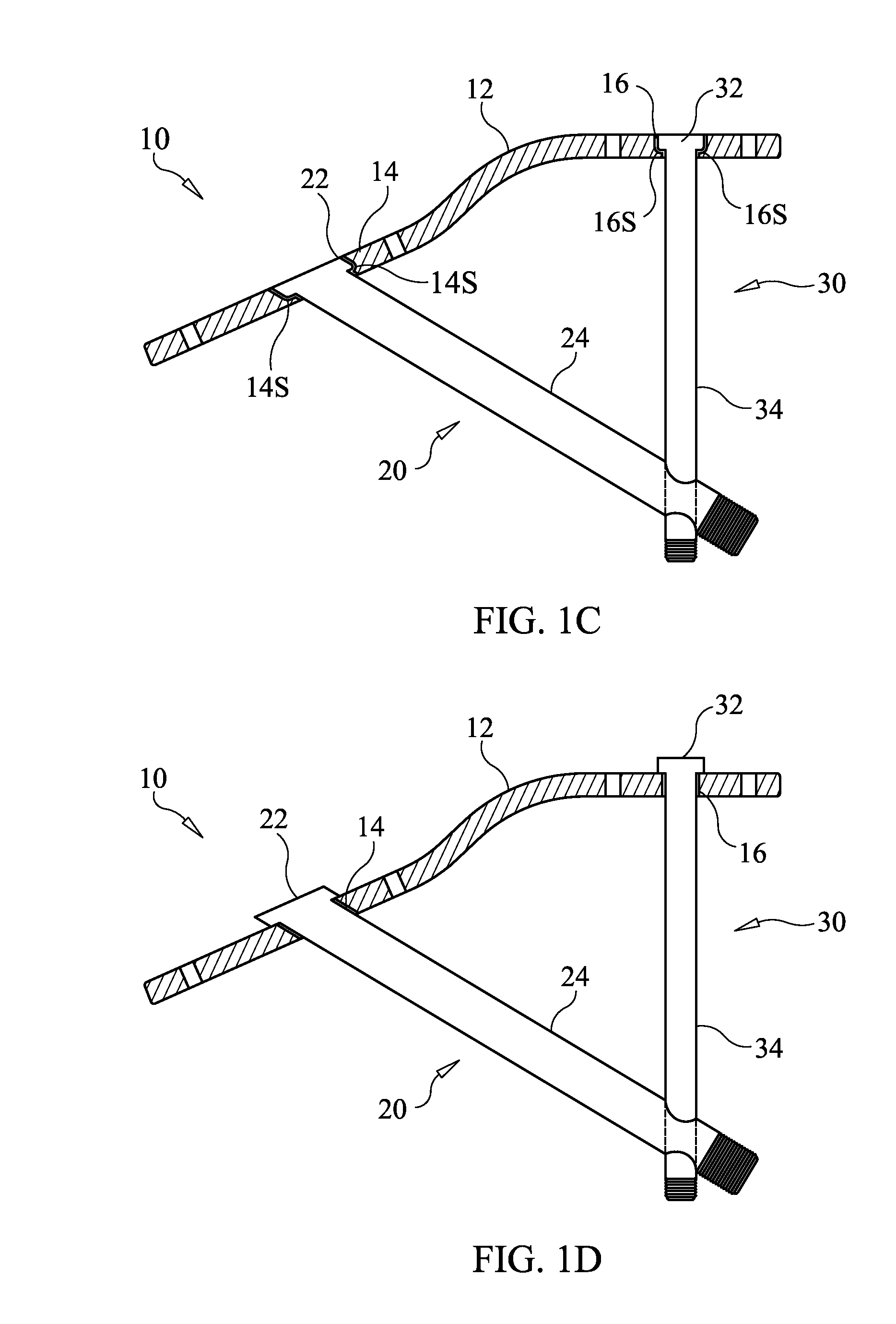
The present invention provides a bone securement apparatus that includes a bone plate, beaming member, and support member. These components form a triangular structure that securely fixes bones or bone fragments together. The apparatus can be used in various procedures such as joint replacement or fracture repair. The technical effects of this invention include improved stability and reduced risk of complications during surgery, as well as improved outcomes and reduced recovery time for patients.

Problems solved by technology

Technically, the above-mentioned types of surgery are complicated by the reality of weight bearing of the extremity.
The most salient issue involved with healing of foot osteotomies is the complex loadbearing which is seen in the foot uniquely.
However, when they lose their function, the articular surfaces are destroyed rather quickly by the unremitting forces of tension on the plantar surfaces and compression on the dorsal surfaces of the ligaments and their attendant bones.
Unfortunately, this method has its limitations as well since most patients are unable to stay off their feet for 6 weeks.
Noncompliance with the requirement to stay off the foot typically results in failure of the procedure.
External fixation has its limitations as well.
Most surgeons do not want to use external fixation because of its technical difficulty, its foreboding appearance, and the requisite constant follow-up during the perioperative period in the doctor's office, which may be financially unreasonable for some practitioners.
Nevertheless locking plates have not been suggested to be tenable for immediate weight bearing even on a limited basis after for reconstruction.
Both the plate fixation lapidus and crossing screw fixation for lapidus procedures (shown in FIGS. 3 and 4, respectively) have limitations in view of the substantial stresses that are applied to those foot bones during normal ambulation by a patient.
Accordingly, in each example, there is limited effectiveness for these repair types of surgery.
While this “truss” formation may provide additional support to the compression forces experienced in the femur, this construction does nothing to provide further support for tension forces such as those experienced in the foot under load bearing.

Method used


Image

  • Bone Securement Apparatus and Method
  • Bone Securement Apparatus and Method
  • Bone Securement Apparatus and Method

Examples


Embodiment Construction

[0055]Before the present apparatus and methods are described, it is to be understood that this invention is not limited to particular embodiments described, as such may, of course, vary. It is also to be understood that the terminology used herein is for the purpose of describing particular embodiments only, and is not intended to be limiting, since the scope of the present invention will be limited only by the appended claims.

[0056]Where a range of values is provided, it is understood that each intervening value, to the tenth of the unit of the lower limit unless the context clearly dictates otherwise, between the upper and lower limits of that range is also specifically disclosed. Each smaller range between any stated value or intervening value in a stated range and any other stated or intervening value in that stated range is encompassed within the invention. The upper and lower limits of these smaller ranges may independently be included or excluded in the range, and each range ...


PUM


Abstract

A bone securement apparatus includes a bone plate configured and dimensioned to be applied across a joint of at least two bones or a space between at least two bone fragments. The bone plate includes first and second openings. A beaming member is configured to pass through the first opening, and the beaming member includes a third opening. A support member is configured to pass through the second opening and the third opening.

Description

FIELD OF THE INVENTION[0001]The present invention relates to the field of fixture devices for bones for use in surgical procedures.BACKGROUND OF THE INVENTION[0002]Various orthopedic surgical procedures require the locking or securing together of adjacent bones or broken bones. In the field of foot and ankle surgery, indications for reconstruction including osteotomy or arthrodesis are well documented in the medical literature as the standard to alleviate pain and infection, minimize limb loss, and maximize physical capacity to return to all activities of daily living or sports.[0003]Technically, the above-mentioned types of surgery are complicated by the reality of weight bearing of the extremity. The most salient issue involved with healing of foot osteotomies is the complex loadbearing which is seen in the foot uniquely. Specifically, body weight axes of force vector down whereas a supporting surface, i.e. the floor, pushes back up. A bending moment is created along the medial an...

Claims


Application Information

Patent Timeline
IPC IPC(8): A61B17/68A61B17/86A61B17/80
CPCA61B17/683A61B17/8061A61B2017/8655A61B17/8057A61B17/86
Inventor GRANT, WILLIAM P.
Owner GRANT WILLIAM P
Learn More