Collapsible buttstock with automatic deployment

a buttstock and automatic deployment technology, applied in the field of buttstocks, can solve the problems of limiting the selection of firearms to one with shorter effective range and less accuracy, affecting the operation of firearm operators, and meeting limited weight and space requirements

Active Publication Date: 2017-01-26
IRVIN ROBERT +1
View PDF7 Cites 27 Cited by
  • Summary
  • Abstract
  • Description
  • Claims
  • Application Information

AI Technical Summary

Benefits of technology

[0012]In certain aspects, the first housing comprises three openings that longitudinally traverse the housing, one for the buffer tube and two for the guide rods. The first housing also comprises an alignment pin protruding from the housing front side facing the firearm, the function of the alignment pin is to maintain the orientation of the housing and the firearm and avoid inadvertent rotation of the housing.

Problems solved by technology

Space, and to a lesser extent weight, limitations may constrain the firearm selection to one with shorter effective range and less accuracy, such as a submachine gun or even a handgun when space requirements are exceedingly restricted.
This immediately puts the firearm operator at a disadvantage when facing an enemy with superior firearm capability.
However, the conventional buttstock (FIG. 1a) presents a deterrent to meeting limited weight and space requirements.
However, when the need arises to deploy a collapsible buttstock, there is limited time to react and get the gun in a fire ready position.
The firearm operator might be in a stressful situation or even taking fire from an enemy.
Deploying the collapsible buttstock under such circumstances becomes an ordeal.
Even if the firearm operator is able to deploy the collapsible buttstock, valuable time will have been spent extending the collapsible buttstock, time in which the operator is not firing and possibly taking fire.

Method used


Image

  • Collapsible buttstock with automatic deployment
  • Collapsible buttstock with automatic deployment
  • Collapsible buttstock with automatic deployment

Examples


Embodiment Construction

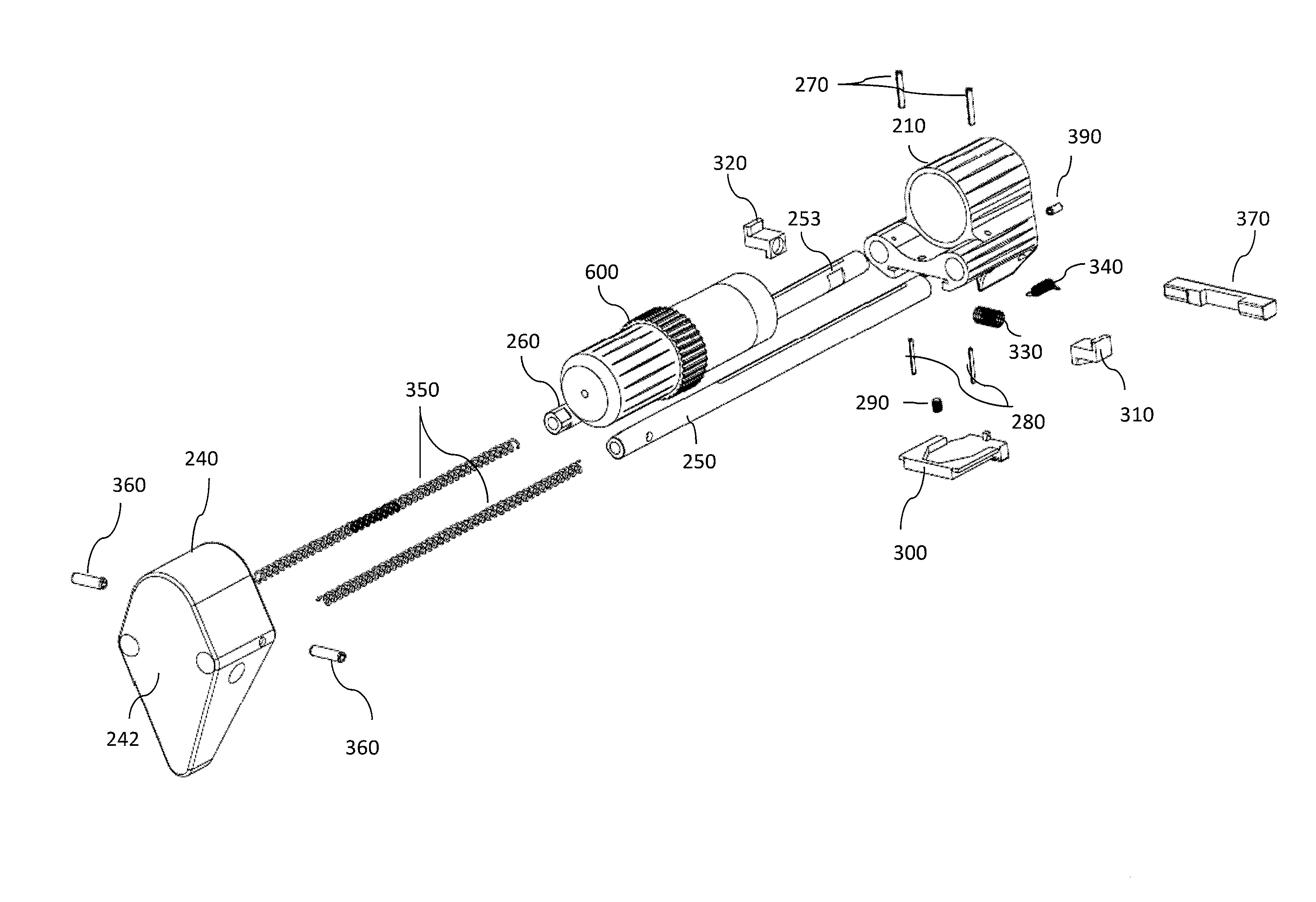
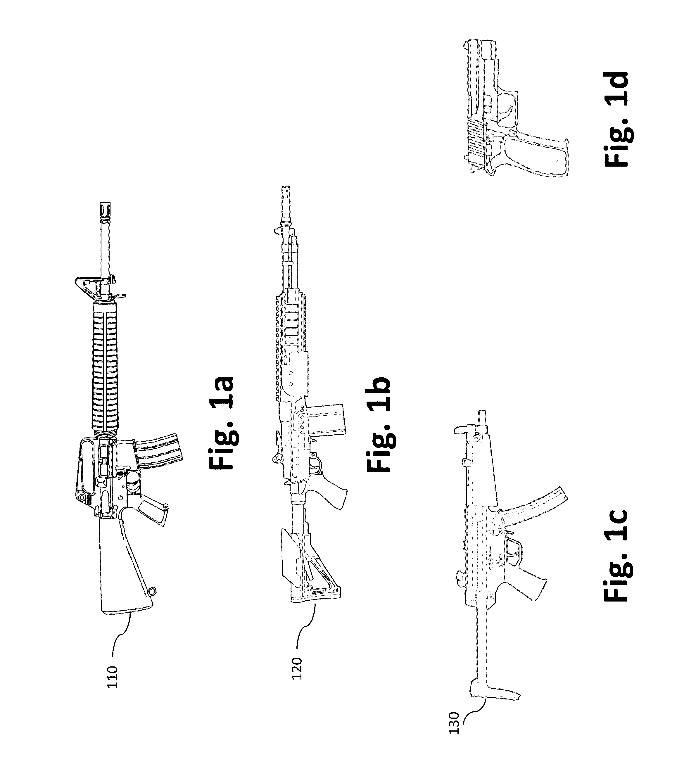
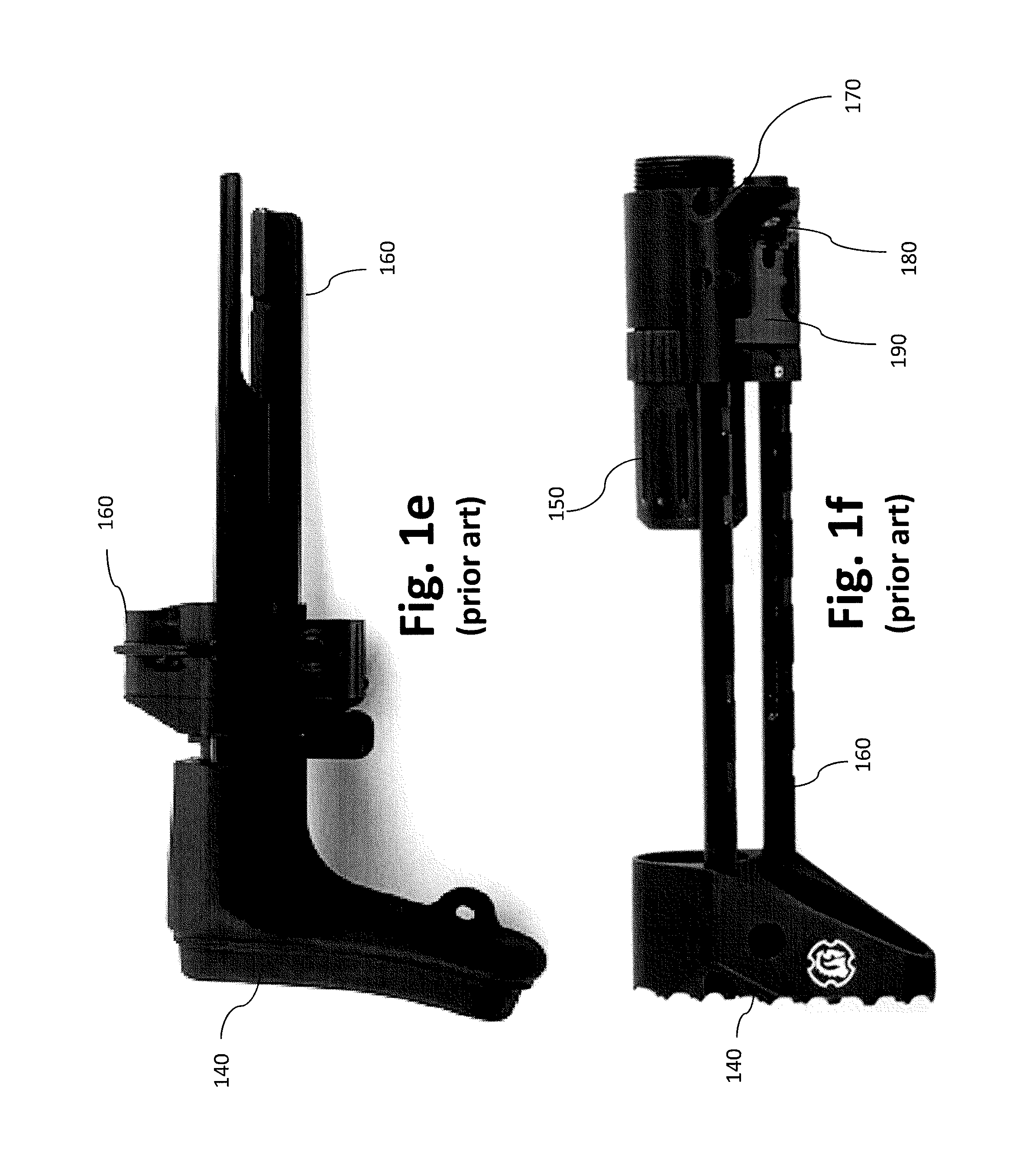
[0101]The present disclosure is directed to a Collapsible buttstock with Automatic deployment (CBAD) device and CBAD adapter mechanism for firearms. Preferred embodiments of the present invention will be described hereinbelow with reference to the figures of the accompanying drawings. In the following description, well-known functions or constructions are not described in detail, since such descriptions would obscure the invention in unnecessary detail.

[0102]For the purpose of promoting an understanding of the principles of the claimed technology and presenting its currently understood, best mode of operation, reference will be now made to the embodiments illustrated in the drawings and specific language will be used to describe the same. It will nevertheless be understood that no limitation of the scope of the claimed technology is thereby intended, with such alterations and further modifications in the illustrated device and such further applications of the principles of the claim...


PUM


Abstract

A collapsible buttstock with automatic deployment has a housing with an opening providing clearance for a buffer tube. Rods slidably couple through respective openings in the housing; the rods each having a hollow cavity accommodating biasing structure for exerting a biasing force against a respective attachment member. A locking element has locking blocks, each engaging a respective one of plural notches on the rods, for locking the rods to an operator support buttstock element, each of the locking blocks comprising a tapered surface. A release trigger with a contoured step engages the tapered surfaces of the locking blocks. When the release trigger is moved, the contoured step engages the tapered surfaces to push locking blocks away from engagement with the notches on the rods, thus allowing the biasing member in each rod to push the respective rod and the operator support buttstock element away from the housing.

Description

[0001]This application is a non-provisional of U.S. Patent Appln. No. 62 / 195,114, filed Jul. 21, 2015 the contents of which are incorporated herein by reference.FIELD OF THE INVENTION[0002]The invention is directed to a collapsible buttstock attached to a firearm having an energy storage device, which, upon release of the stored energy, automatically and rapidly moves the butt stock from a locked collapsed position to a fully or partially extended position—thus enabling the firearm operator to position the buttstock in the proper shoulder location and allowing the operator to better control the firearm and make accurate shots.BACKGROUND OF THE INVENTION[0003]Members of the armed forces and law enforcement worldwide utilize several types of firearms, which generally fall into three main categories, hand guns (FIG. 1d), submachine guns (FIG. 1c) and rifles (FIG. 1a). Carbines may also be considered under the rifle category and the terms carbine and rifle may be used interchangeably he...

Claims


Application Information

Patent Timeline
Patent Type & Authority Applications(United States)
IPC IPC(8): F41C23/04
CPCF41C23/04F41C23/06
Inventor IRVIN, ROBERTBUSH, GEORGE W.ALKHALAILEH, SAMERCOX, JOSHUA K.
Owner IRVIN ROBERT
Why Eureka
Try Eureka