Vehicle-mounted camera case and vehicle-mounted camera device

a camera device and camera case technology, applied in vehicle maintenance, vehicle cleaning, instruments, etc., can solve the problems of insufficient visibility and inconvenient capture of images, and achieve the effect of suppressing an increase in the temperature of the camera and inhibiting dus

Inactive Publication Date: 2017-02-02
DENSO CORP
View PDF4 Cites 15 Cited by
  • Summary
  • Abstract
  • Description
  • Claims
  • Application Information

AI Technical Summary

Benefits of technology

[0012]When the vehicle moves, dust, dirt, and other materials are occasionally scattered from the road surface. The scattered materials, such as dust and dirt, are blocked by the air discharged from the air outlet and unlikely to reach the lens of the camera, which is positioned above the air outlet. This inhibits the dust, dirt, and other materials, which are scattered from the road surface, from adhering to the lens of the camera.
[0013]Further, even if raindrops enter the vehicle-mounted camera case through the air inlet, the raindrops are blocked by the shield, which protrudes downward from the upper po

Problems solved by technology

When the raindrops adhere to the lens, the visibility of the captured image becomes inadequate.
However, dust, dirt, and other

Method used


Image

  • Vehicle-mounted camera case and vehicle-mounted camera device
  • Vehicle-mounted camera case and vehicle-mounted camera device
  • Vehicle-mounted camera case and vehicle-mounted camera device

Examples


first embodiment

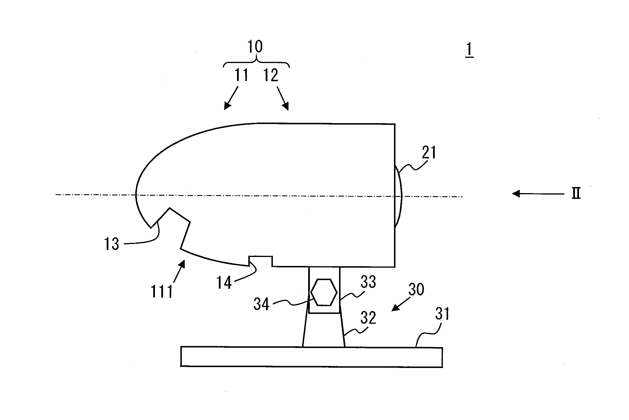
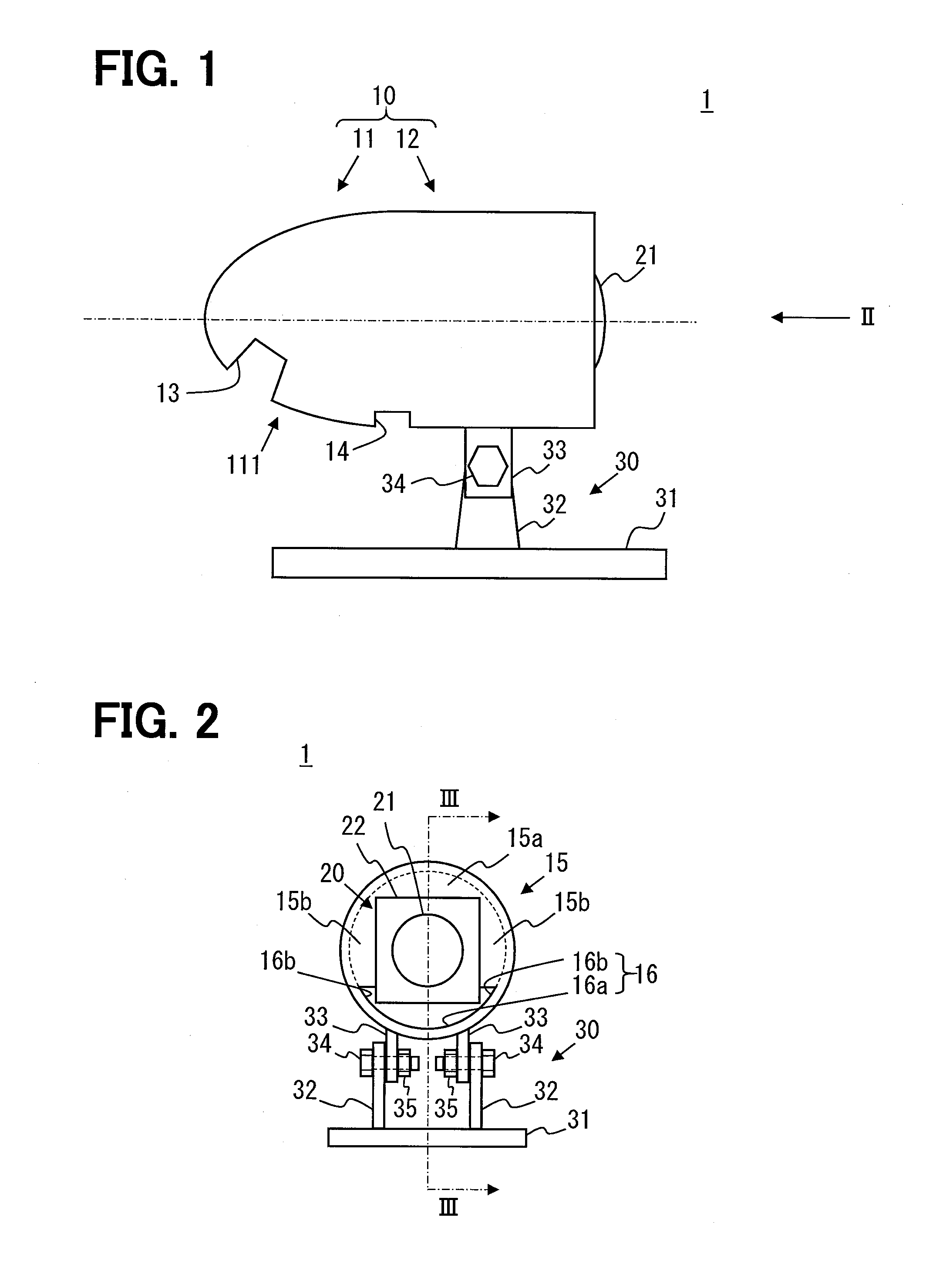
[0029]Embodiments of the present disclosure will now be described with reference to the accompanying drawings. As illustrated in FIGS. 1 and 2, a vehicle-mounted camera device 1 according to a first embodiment includes a vehicle-mounted camera case (hereinafter simply referred to as the camera case) 10 having a cannon-shell-shape. The surface of the camera case 10 is coated with publicly known heat-proof paint such as acrylic resin paint with ceramic beads.

Configuration of Vehicle-Mounted Camera Device 1

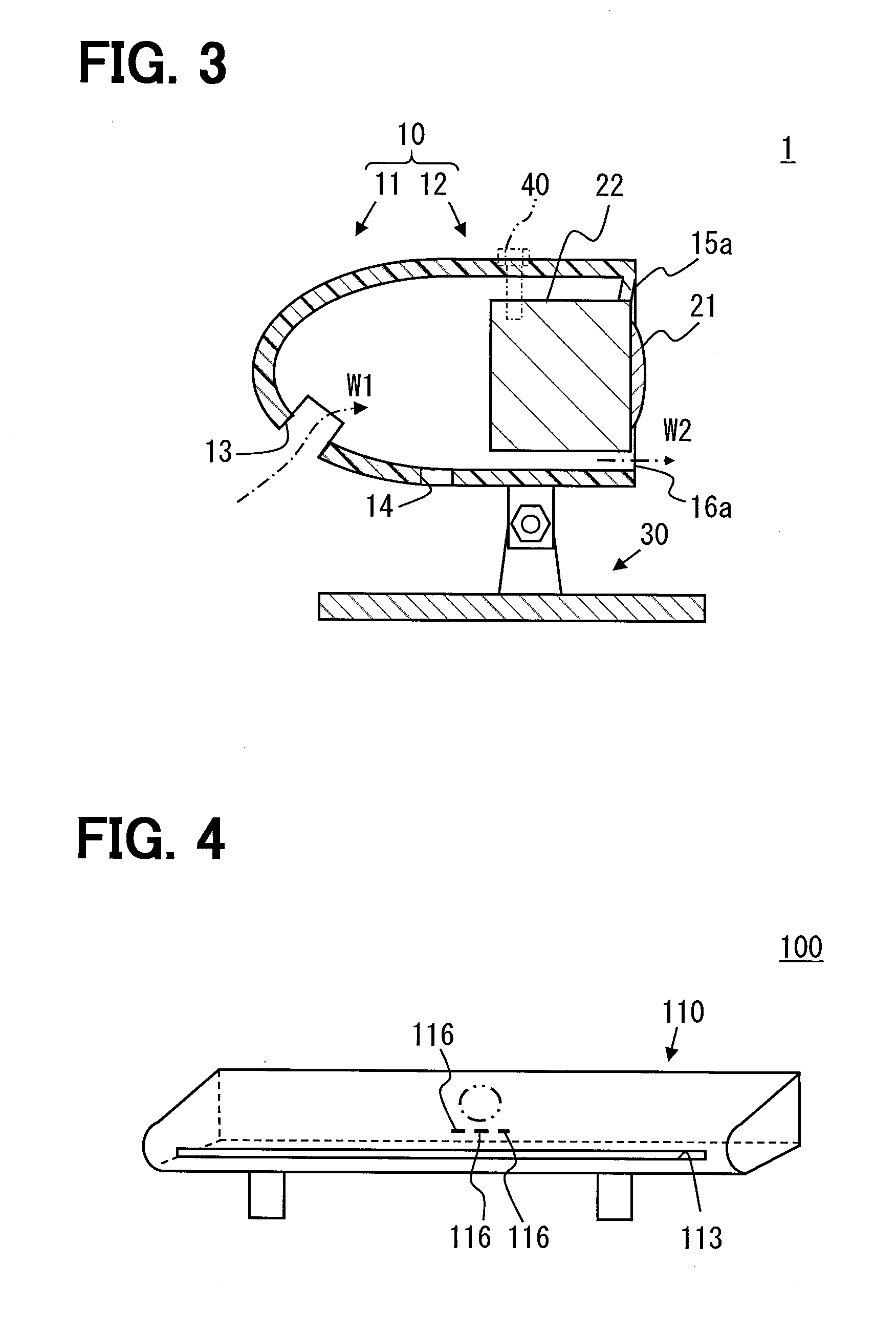
[0030]As illustrated in FIG. 3, a front portion 11 of the camera case 10 is open toward a rear portion 12 and a cross-section of the front portion 11 taken along a plane containing a central axis has substantially a U shape. The rear portion 12 is cylindrical and has the same diameter as the rear end of the front portion 11.

[0031]As mentioned above, the cross-section of the front portion 11 taken along the plane containing the central axis (and running parallel to the central axis) i...

second embodiment

[0055]A second embodiment will now be described. In the description of the second and subsequent embodiments, elements designated by the same reference numerals as the elements described in conjunction with foregoing embodiments are identical with the corresponding elements unless otherwise specifically stated. Further, when only a specific portion of the configuration is described, the foregoing embodiments are applicable to the other portion of the configuration.

[0056]As illustrated in FIG. 4, a camera case 110 included in a vehicle-mounted camera device 100 according to the second embodiment is capable of functioning as a spoiler and secured to a trunk lid. An air inlet 113 is formed in the front end face of the camera case 110.

[0057]The camera 20 is omitted from FIG. 4. However, the position at which the camera 20 is mounted is indicated by a two-dot chain line circle. As is obvious from the position of the circle, the camera 20 is disposed at the longitudinal center of the came...

third embodiment

[0060]As illustrated in FIG. 5, a camera case 210 included in a vehicle-mounted camera device 200 according to a third embodiment is formed of a front casing member 211 and a rear casing member 212. The inside diameter of the open end of the front casing member 211 is substantially equal to the outside diameter of the rear casing member 212. The camera case 210 is formed by fitting the open end of the front casing member 211 onto the front end of the rear casing member 212. As is the case with the first embodiment, the air inlet 13 is formed in the front casing member 211. The water drain hole 14 is also formed in the front casing member 211.

[0061]The rear casing member 212 includes a cylindrical portion 212a and a shield 215. The shield 215 is disposed at the front end of the cylindrical portion 212a and protruded downward from an upper portion of the cylindrical portion 212a. Although not shown in FIG. 5, the lower surface 215a of the shield 215 is formed between one end of the cy...


PUM


Abstract

A vehicle-mounted camera case mounted on an outer surface of a vehicle to house a camera is provided. The vehicle-mounted camera case includes an air inlet, an air outlet, and a shield. The air inlet takes air into the vehicle-mounted camera case when the vehicle moves forward. The air outlet discharges the air taken in from the air inlet and is formed in at least a lower portion of a rear end face of the vehicle-mounted camera case. The shield protrudes downward from an upper portion of the vehicle-mounted camera case.

Description

CROSS REFERENCE TO RELATED APPLICATION[0001]This application is based on Japanese Patent Application No. 2013-244288 filed on Nov. 26, 2013, the disclosure of which is incorporated herein by reference.TECHNICAL FIELD[0002]The present disclosure relates to a vehicle-mounted camera case and to a vehicle-mounted camera device provided with the vehicle-mounted camera case.BACKGROUND ART[0003]There is a widely known device that uses a vehicle-mounted camera to capture an image representing a rear or side view from a vehicle and displays the captured image on a monitor in the vehicle. When such a device is used, each of the cameras is housed in a case and mounted on the roof of the vehicle or other external surface of the vehicle as described, for example, in Patent Literatures 1 and 2.[0004]The case described in Patent Literature 1 has a transparent window. The window is located above the lens of the camera. The camera is entirely covered by the case. The case described in Patent Literat...

Claims


Application Information

Patent Timeline
IPC IPC(8): B60R11/04
CPCB60R2011/004B60R11/04B62D37/02B60S1/54B60S1/56G03B17/08G02B27/0006H04N23/51
Inventor MATSUMOTO, MUNEAKI
Owner DENSO CORP
Why Eureka
Try Eureka