Well casing/tubing disposal

a technology for disposal of well casings and tubings, which is applied in the direction of sealing/packing, borehole/well accessories, insulation, etc., can solve the problems of time-consuming, expensive, and inconvenient mechanical approaches, and achieve the effect of convenient deployment of repair tools

Active Publication Date: 2017-02-02
BISN TEC
View PDF3 Cites 26 Cited by
  • Summary
  • Abstract
  • Description
  • Claims
  • Application Information

AI Technical Summary

Benefits of technology

[0063]In the case were an inner tubing is cleared the removal of the tubing from within th

Problems solved by technology

Such mechanical approaches can be time consuming and, as a result, expensive.
They also produce debris in the form of swarf as the casing is broken down, which can interfere with both the milling/drilling itself and any subsequent plugging operation.
In addition, any swarf produced is classed as contaminated material that needs to be disposed of in accordance with strict regulatio

Method used


Image

  • Well casing/tubing disposal
  • Well casing/tubing disposal

Examples


Embodiment Construction

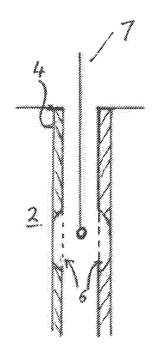
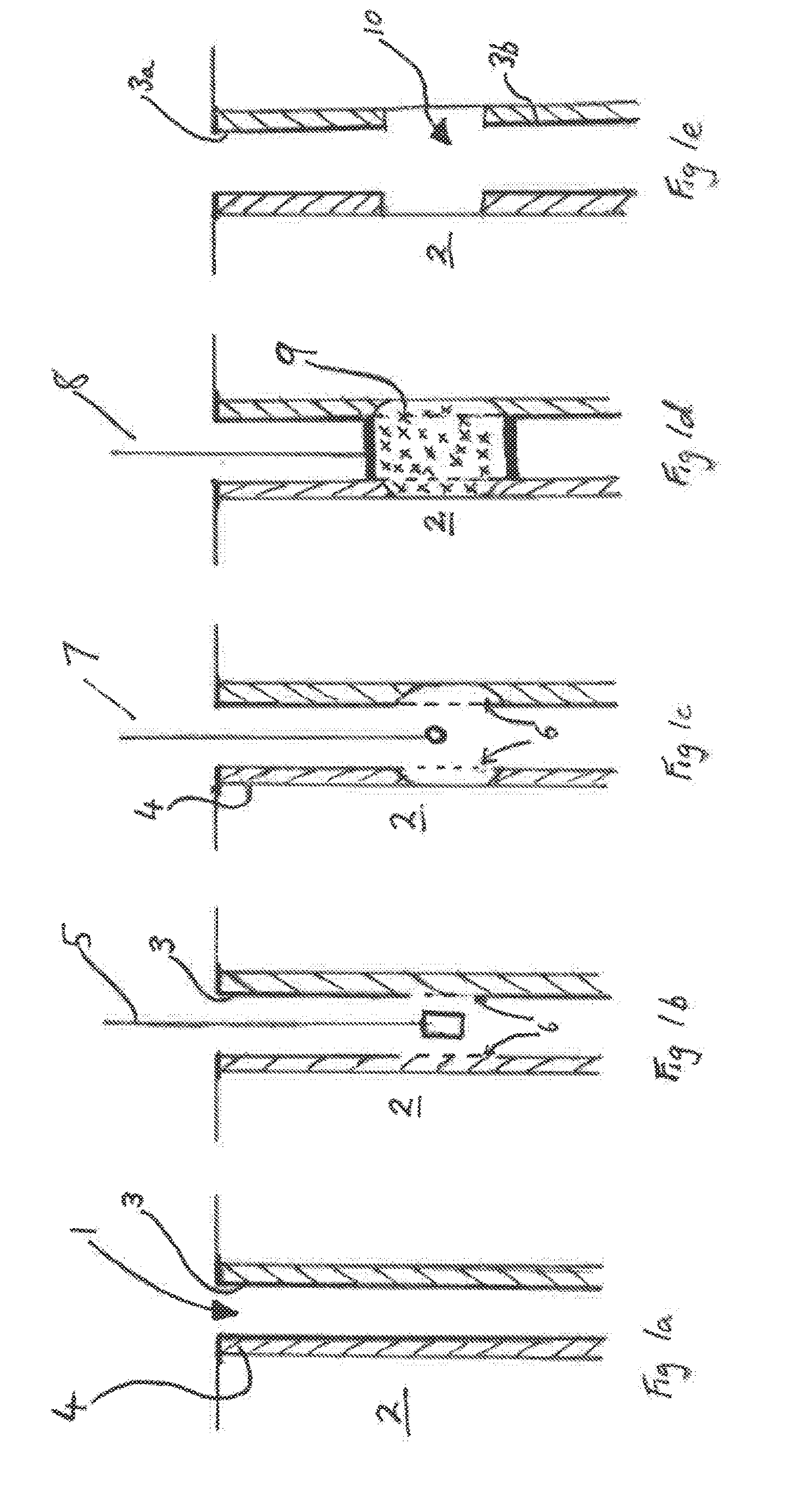
[0070]So that the general concept of the present invention might be better understood an exemplary process of the well casing / tubing disposal method of the present invention will be described with reference to FIGS. 1a-1e.

[0071]The skilled person will appreciate from the following description, that certain steps shown in the drawings may be omitted without departing from the general inventive concept. Further, the skilled person will also appreciate that additional steps to those shown may also be used to achieve additional benefits.

[0072]Turning now to FIGS. 1a, 1b, 1c, 1d and 1e, which show in order the steps involved in removing / disposing of a portion of a well casing / tubing so as to create an exposed region capable of receiving a well plug that can be used to form a plug across the entire cross-section of a well bore hole (i.e. from the rock formation on one side of the borehole to the rock formation on the other side of the borehole).

[0073]It will be appreciated that although ...


PUM


Abstract

A method of clearing well casing (3) or tubing from a target region of an oil/gas well (1) borehole is provided. The clearance of the oil/gas well bore hole being achieved by employing chemical agents (9) that consume, weaken or melt the well casing/tubing. In some aspects of the method the well casing is cleared to expose the rock formation within which the well borehole is formed so that the rock formation can be accessed from within the well casing/tubing. In other aspects of the method the removal of inner tubing structures is used to facilitate the unimpaired deployment of repair tools down the well borehole.

Description

FIELD OF THE INVENTION[0001]The present invention relates in general to P&A (plugging and abandonment) and work-over operations for underground conduits such as oil / gas wells, and in particular to the removal or disposal of oil well elements such as well casing / tubing.BACKGROUND OF THE INVENTION[0002]Once an oil / gas well has come to the end of its useful life, the well needs to be safely decommissioned. An important aspect of decommissioning is the plugging and abandonment (P&A) of the well. The plugging of an abandoned well is necessary to seal it off and prevent the escape of hydrocarbons and gases from within the well.[0003]Various methods are known in the art for providing both permanent and removable plugs within abandoned wells. In some situations a plug may be deployed within a well casing that is itself deployed within a bore hole within the ground.[0004]In other situations it is desirable to deploy a plug which extends across the whole cross-section of a bore hole. In these...

Claims


Application Information

Patent Timeline
IPC IPC(8): E21B33/138E21B29/10E21B36/00E21B29/02E21B37/00
CPCE21B33/138E21B29/02E21B37/00E21B33/16E21B36/001E21B36/003E21B29/10E21B36/008E21B29/06
Inventor CARRAGHER, PAUL
Owner BISN TEC
Why Eureka
Try Eureka