
Toroidal continuously variable transmission

a technology of toroidal and continuously variable transmission, which is applied in the direction of engine components, mechanical equipment, gearing, etc., can solve the problems of reducing the efficiency of the electric power generation device, and achieve the effect of effectively using a space and reducing the loss of oil agitation resistan

Active Publication Date: 2017-02-02
KAWASAKI HEAVY IND LTD
View PDF0 Cites 0 Cited by
  • Summary
  • Abstract
  • Description
  • Claims
  • Application Information

AI Technical Summary

Benefits of technology

The patent text describes a toroidal continuously variable transmission with a unique design that can improve efficiency and reduce oil agitation loss while maintaining high reliability. The design includes separate input discs with back surface cylinder walls that can support a bearing and an input gear. This configuration allows for a reduction in gear size and speed, resulting in a reduction of oil agitation resistance and ultimately lower loss. The use of annular support spacers between the input discs and the back surface of the input gear can further stabilize the input discs in the axial direction.

Problems solved by technology

As a result, oil agitation loss by the gear increases, so that the efficiency of the electric power generating device decreases.

Method used


Image

  • Toroidal continuously variable transmission
  • Toroidal continuously variable transmission
  • Toroidal continuously variable transmission

Examples


Embodiment Construction

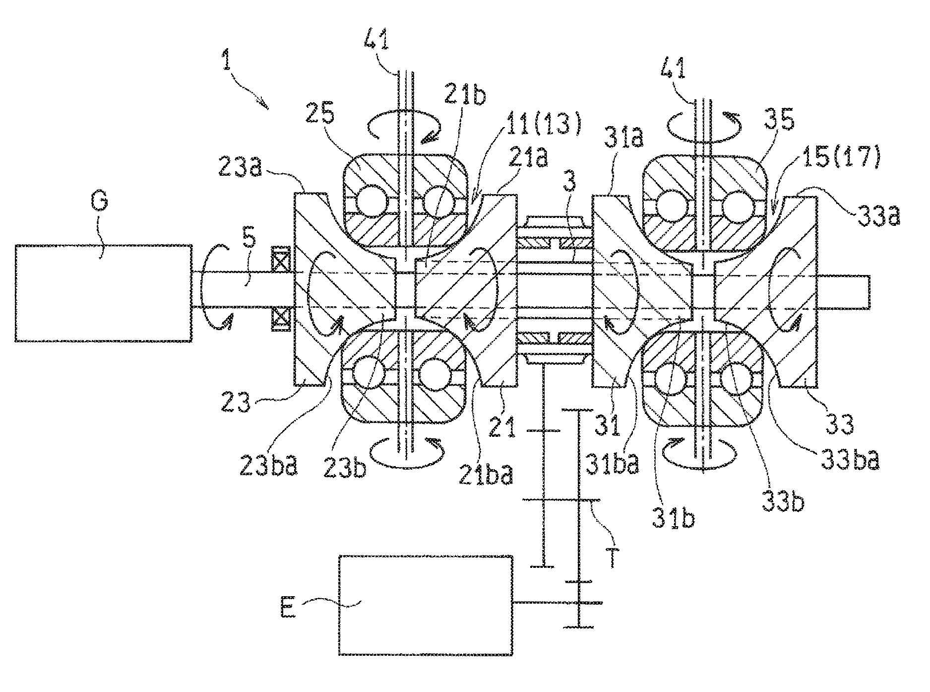
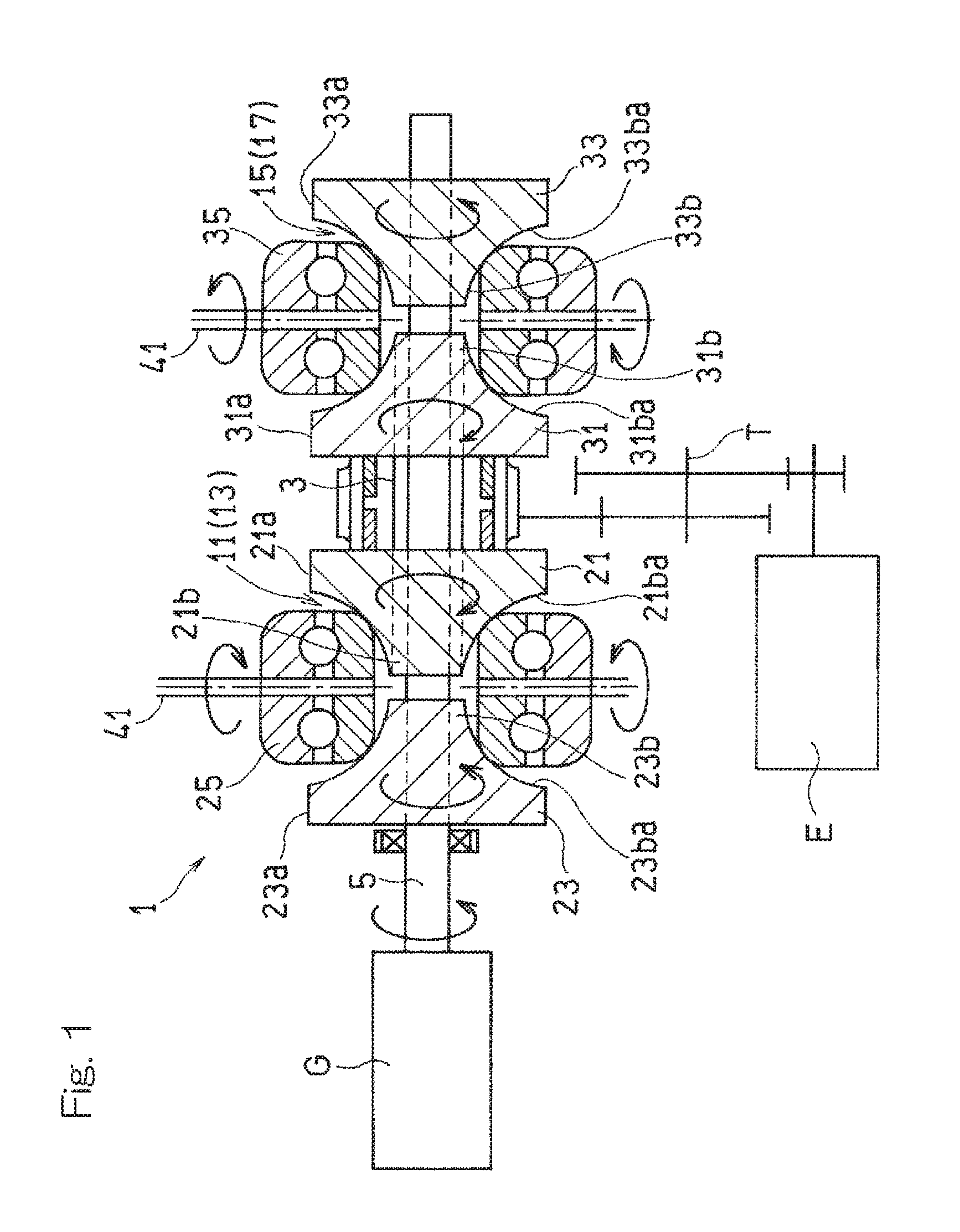
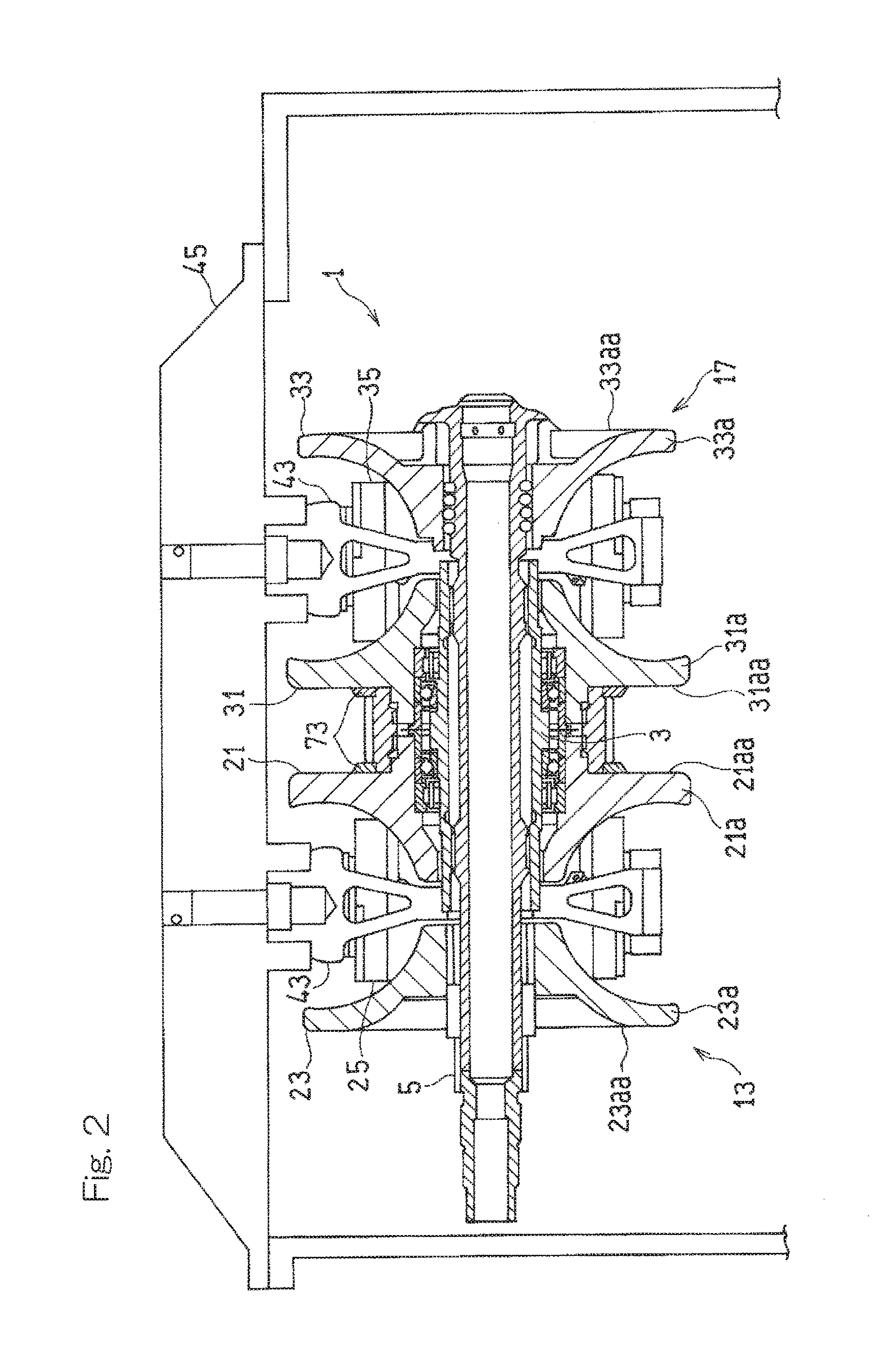
[0024]Hereinafter, embodiments of the present invention will be described with reference to the drawings. FIG. 1 is a longitudinal cross-sectional view schematically showing a toroidal continuously variable transmission (hereinafter, referred to simply as a “continuously variable transmission”) 1 according to a first embodiment of the present invention. The continuously variable transmission 1 is provided between an aircraft engine E that is a drive source and a generator G that is a load device driven by the engine E. The continuously variable transmission 1 transmits a driving force of the engine E to the generator G while keeping a rotation rate of the generator G constant. A constant frequency generator mainly includes the continuously variable transmission 1 and the generator G.

[0025]The engine E is connected to the input shaft 3, which is formed so as to be hollow, of the continuously variable transmission 1 via a power transmission mechanism T. Power inputted to the input sha...


PUM


Abstract

In a continuously variable transmission including: a first transmission unit including a first input disc and a first output disc disposed coaxially and a power roller tiltably interposed between these discs; and a second transmission unit disposed coaxially with the first transmission unit, including a second input disc and a second output disc disposed coaxially and a second power roller tiltably interposed between these discs, and disposed such that a back surface of the second input disc is opposed to a back surface of the first input disc, a tubular back surface cylinder wall is provided on each of the back surfaces of the first input disc and the second input disc so as to project therefrom.

Description

CROSS REFERENCE TO THE RELATED APPLICATION[0001]This application is a continuation application, under 35 U.S.C. §111(a), of international application No. PCT / JP2015 / 061395, filed Apr. 13, 2015, which claims priority to Japanese patent application No. 2014-082827, filed Apr. 14, 2014, the disclosure of which are incorporated by reference in their entirety into this application.BACKGROUND OF THE INVENTION[0002]Field of the Invention[0003]The present invention relates to a structure of a toroidal continuously variable transmission for use in, for example, an electric power generating device for an aircraft.[0004]Description of Related Art As an electric power generating device for an aircraft, it is known to use a constant frequency generator (IDG) that operates while keeping a rotation rate (frequency) of a generator constant even when a rotation rate of an aircraft engine, which is a drive source, varies. As a transmission for keeping a rotation rate of the generator constant in the ...

Claims


Application Information

Patent Timeline
Patent Type & Authority Applications(United States)
IPC IPC(8): F16H15/38F16C19/54F16H37/02
CPCF16H15/38F16H37/021F16C2361/00F16H2015/383F16C19/541
Inventor TANAKA, KENICHIROIMAI, HIDEYUKIGOI, TATSUHIKOFUJII, ISAO
Owner KAWASAKI HEAVY IND LTD
Learn More