
M-type pulverized coal boiler suitable for ultrahigh steam temperature

a pulverized coal boiler and ultrahigh steam technology, which is applied in the direction of combustion types, ignition automatic control, lighting and heating apparatus, etc., can solve the problems of high cost of nickel base alloy materials, increase the cost of the four high-temperature pipelines between the main steam/reheated steam and the steam turbine to about 2.5 billion rmb, and achieve the effect of high manufacturing cost of a boiler

Active Publication Date: 2014-12-09
HUANENG CLEAN ENERGY RES INST
View PDF16 Cites 0 Cited by
  • Summary
  • Abstract
  • Description
  • Claims
  • Application Information

AI Technical Summary

Benefits of technology

The patent discloses a new type of pulverized coal boiler that is suitable for ultrahigh steam temperature. By arranging a middle flue between the outlet of the hearth and the tail downward flue, the boiler can achieve higher efficiency and lower manufacturing costs. The boiler also includes a denitration system and an air preheater that can be arranged in the tail downward flue, solving the problem of difficult arrangement in other boilers. The technical effects include reduced manufacturing costs, improved efficiency, and reduced on-way resistance and thermal loss.

Problems solved by technology

However, the nickel base alloy material is very expensive, more than 15 times of the price of a present common iron base heat resistant alloy steel of level 600° C. According to the system deployment mode of a present common thermal power generating unit, if the nickel base alloy material is adopted, taking two 1000 MW ultra-supercritical units for example, just the cost of the four high-temperature pipelines between the main steam / reheated steam and a steam turbine would be increased to about 2.5 billion RMB from the present 300 million RMB.
In addition, the manufacturing cost is increased when the high-temperature parts of the boiler and the steam turbine adopt a heat resistant alloy, finally the overall cost of the advanced ultra-supercritical unit of level 700° C. would be greatly higher than that of the thermal power generating unit of level 600° C., which limits the application and promotion of the advanced ultra-supercritical thermal power generating unit.
Although the double-reheat method can improve the unit efficiency to a great extent, the complexity of the unit system adopting the double-reheat technology is higher than that of the unit system adopting the single-reheat technology and the investment thereof is greatly increased, which limits the application of the double-reheat system.
A Chinese patent “A novel steam turbine generating unit” with patent number of 200720069418.3 discloses a method for reducing the length and cost of a high temperature and high pressure steam pipeline of a double-reheat unit by distributing a high shafting and a low shafting at different height; however, since the high shaft formed by a high pressure cylinder and a generating unit needs to be arranged at a height of about 80 meters, serious problems such as shaking might be caused, and it is needed to solve the technical problems of support and foundation, thus this arrangement method has not been applied.
However, since the eddy and disturbance of the flue gas is severe, the flow uniformity of the flue gas is poor, and it is easy to cause uneven heating of the heating surfaces, thus great temperature deviation is caused; and the boiler is heavily abraded when inferior fuel is combusted.
However, the area occupied by the T-type boiler is greater than that occupied by the π-type boiler, the gas-water pipeline connection system is complex and the metal consumption is big, thus the T-type boiler is less applied.
No matter what arrangement mode the boiler adopts, due to the need of heat transfer, the high-temperature heating surfaces need to be arranged at an area with high flue gas temperature, while the elevation of the position on which the area with high flue gas temperature is located is high (above 50 to 80 meters), thus the high-temperature steam connection pipeline between the high-temperature heating surface outlet and the steam turbine is very long (for example, for the tower type boiler, the length of a single high-temperature steam pipeline reaches 160 to 190 meters), and the cost is high, and the application of the double-reheat technology is limited.
Besides, it takes a relatively long time to burn out the pulverized coal in the hearth, thus a relatively high hearth height is needed; however, the increase of the hearth height means the great increase of the manufacturing cost.
Thus, the point on how to prolong the burning time and improve the burnout degree of the pulverized coal particles in the case of not increasing the hearth height also becomes a long-term concerned technical problem in the technical field of boilers.

Method used


Image

  • M-type pulverized coal boiler suitable for ultrahigh steam temperature
  • M-type pulverized coal boiler suitable for ultrahigh steam temperature
  • M-type pulverized coal boiler suitable for ultrahigh steam temperature

Examples


Embodiment Construction

[0059]The embodiment of the disclosure is illustrated below in detail in conjunction with accompanying drawings, but the disclosure can be implemented by multiple modes limited and covered by claims.

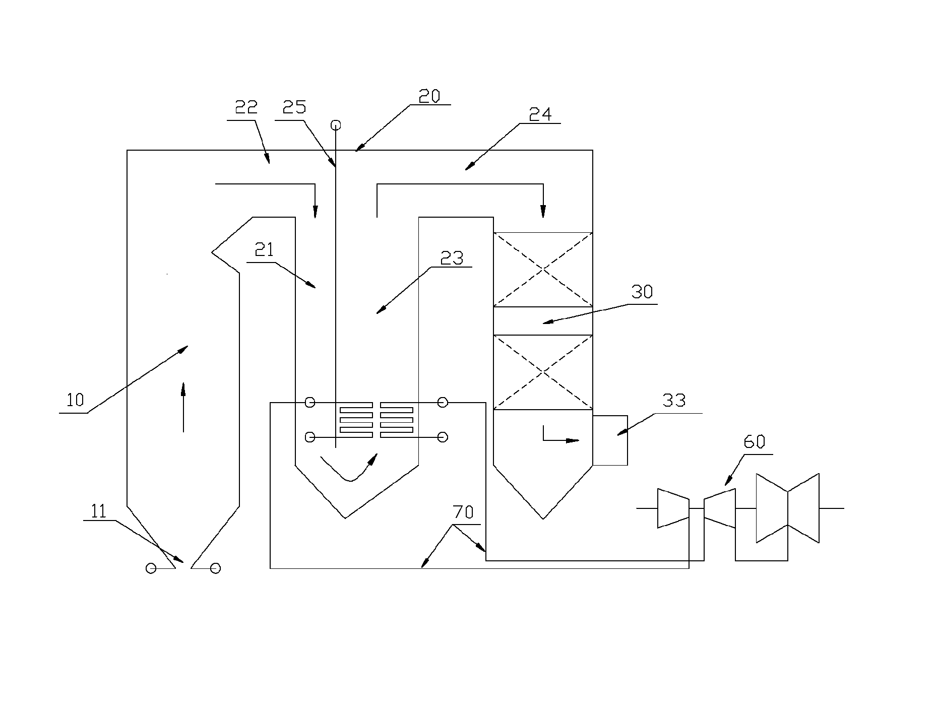
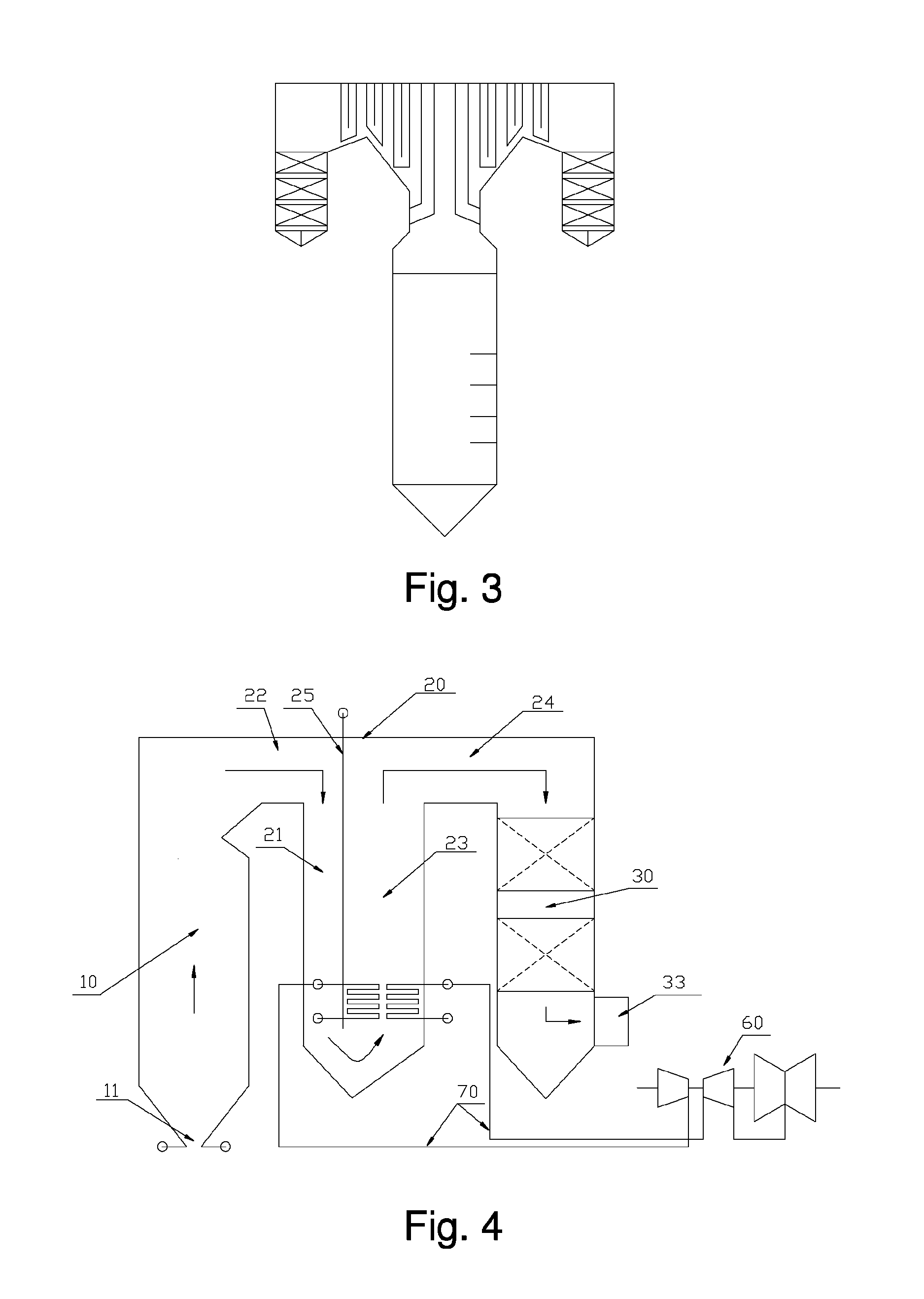
[0060]The disclosure provides a pulverized coal boiler suitable for ultrahigh steam temperature, in particular an M-type pulverized coal boiler suitable for ultrahigh steam temperature. FIG. 4 shows a structure of a pulverized coal boiler in which a hearth outlet downward flue and an upward flue are formed by separating an integrated flue. As shown in FIG. 4, the M-type pulverized coal boiler suitable for ultrahigh steam temperature provided by the disclosure comprises a hearth 10 and a tail downward flue 30 of which the upper end is communicated with the upper end of the hearth 10; the pulverized coal boiler further comprises a middle flue 20 communicated between the hearth 10 and the tail downward flue 30, wherein the middle flue 20 comprises: a hearth outlet downward flue 21 and an up...


PUM


Abstract

The disclosure provides an M-type pulverized coal boiler suitable for ultrahigh steam temperature. The pulverized coal boiler comprises a hearth of which the bottom is provided with a slag hole and a tail downward flue of which the lower part is provided with a flue gas outlet. The pulverized coal boiler further comprises a middle flue communicated between the hearth and the tail downward flue, wherein the middle flue comprises an upward flue and a hearth outlet downward flue of which the bottoms are mutually communicated and the upper ends are respectively communicated with the upper end of the hearth and the upper end of the tail downward flue to form a U-shaped circulation channel. In the pulverized coal boiler provided by the disclosure, the middle flue which extends downwards and can make flue gas flow along the U-shaped circulation channel is arranged between the outlet of the hearth and the tail downward flue, so that high-temperature flue gas from the hearth can be introduced into a position with low elevation through the downward flue, and final-stage convection heating surfaces (such as a high-temperature superheater and a high-temperature reheater) can be arranged at positions with low height, and the length of ultrahigh-temperature steam pipelines between the high-temperature superheater and a steam turbine, and between the high-temperature reheater and the steam turbine can be greatly reduced. Therefore, the manufacturing cost of a boiler unit is obviously reduced.

Description

CROSS-REFERENCE TO RELATED APPLICATIONS[0001]This application is filed under the provisions of 35 U.S.C. §371 and claims the priority of International Patent Application No. PCT / CN2011 / 082086 filed on Nov. 11, 2011 and of Chinese Patent Application No. 201110056111.0 filed on Mar. 8, 2011. The disclosures of the foregoing international patent application and Chinese patent application are hereby incorporated by reference herein in their respective entireties.TECHNICAL FIELD OF THE INVENTION[0002]The disclosure relates to the field of combustion equipment, in particular to an M-type pulverized coal boiler suitable for ultrahigh steam temperature.BACKGROUND OF THE INVENTION[0003]Pulverized coal boiler generator set, as the core technology of thermal power generation, experiences one hundred years of development history. From the subcritical to the supercritical, then to the ultra-supercritical, China's coal-fired power technology gets a rapid development in recent years. The rapid dev...

Claims


Application Information

Patent Timeline
Patent Type & Authority Patents(United States)
IPC IPC(8): F22B29/06F01K7/34F22G1/04F22D1/38F22D1/02F22G7/12F01K13/00
CPCF01K7/34F22D1/02F22G7/12F01K13/006F22G1/04F22B21/345F22B29/06
Inventor JIANG, MINHUAXIAO, PINGJIANG, JIANZHONGZHONG, LI
Owner HUANENG CLEAN ENERGY RES INST
Learn More