
Apparatus and methods for controlling transmission of data

a technology of data transmission and apparatus, applied in the direction of transportation and packaging, marine propulsion, vessel construction, etc., can solve the problems of wired connection wear and several challenges in the transmission of electrical signals between two such parts

Active Publication Date: 2017-02-02
ROLLS ROYCE PLC
View PDF4 Cites 3 Cited by
  • Summary
  • Abstract
  • Description
  • Claims
  • Application Information

AI Technical Summary

Benefits of technology

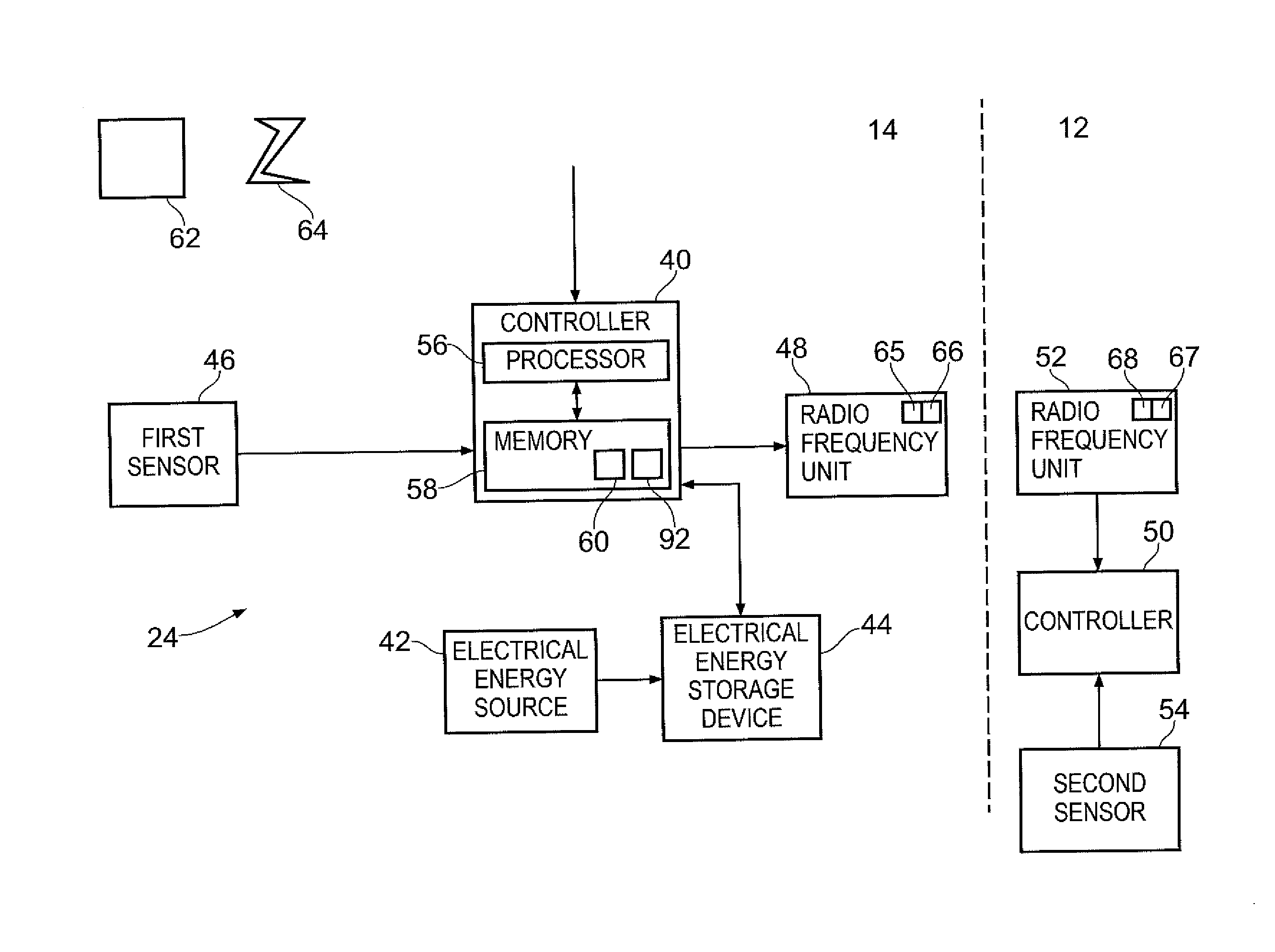
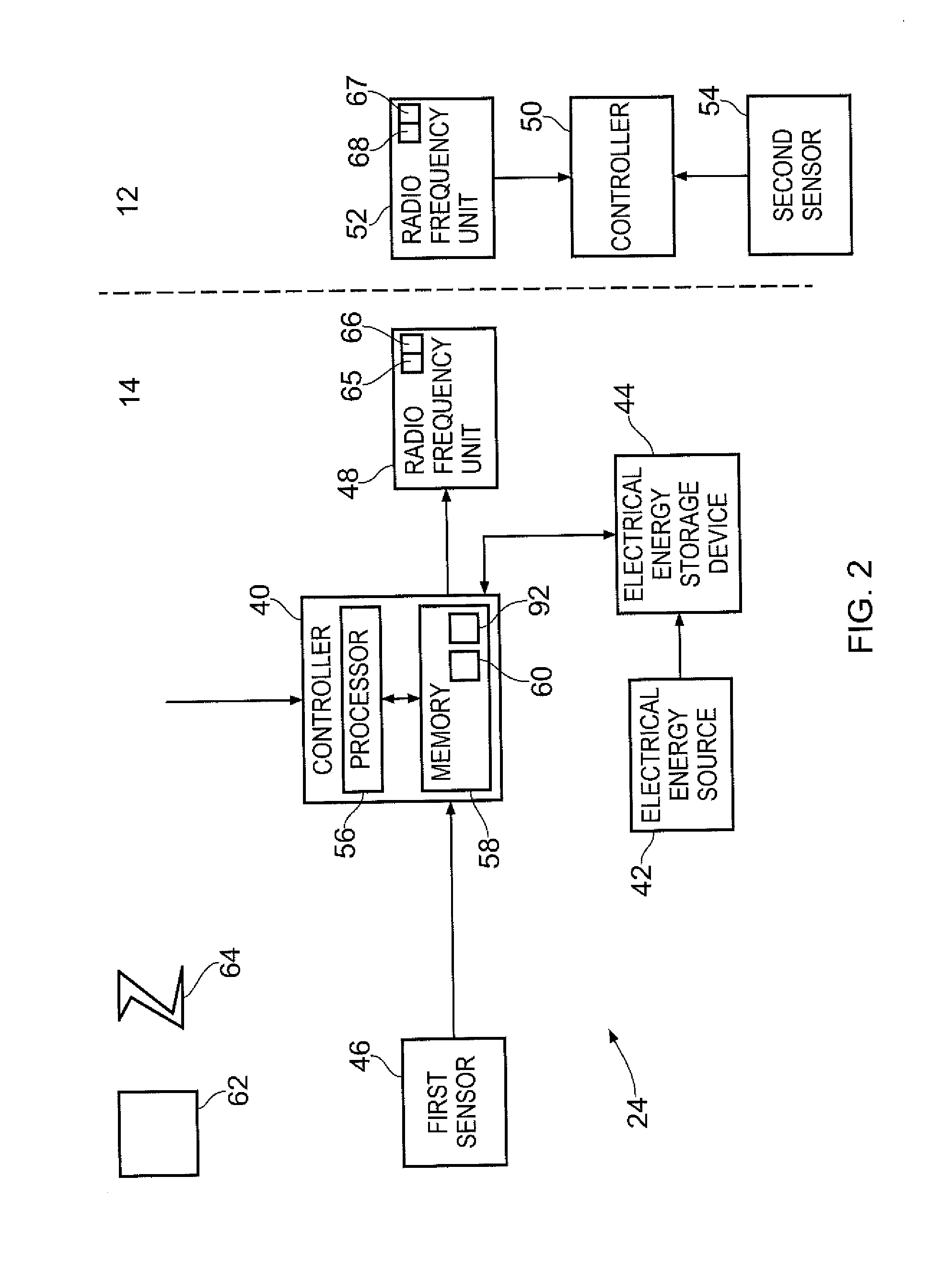
The patent describes an apparatus and method for controlling transmission of data from an azimuth thruster. The apparatus includes a controller that receives data from a sensor, determines if certain criteria are met, and controls the transmission of the data from a first antenna on the lower housing of the azimuth thruster. The method involves determining if electrical power is transferred between two inductors, receiving an activation signal, controlling storage of the data in memory, and controlling transmission of the data from the first antenna in response to a data request signal. The technical effects of the invention include improved data transmission and control over the relative positioning of the antennas, as well as improved operational control and data analysis.

Problems solved by technology

The transfer of electrical signals between two such parts may present several challenges due to the movement of the two parts.
Transferring an electrical signal between a stationary part of the azimuth thruster and a rotatable part of the azimuth thruster may present several challenges.
By way of an example, it may be challenging to transfer an electrical signal via a wired connection between the stationary and rotatable parts because relative movement between the stationary and rotatable parts may cause wear on the wired connection.

Method used


Image

  • Apparatus and methods for controlling transmission of data
  • Apparatus and methods for controlling transmission of data
  • Apparatus and methods for controlling transmission of data

Examples


Embodiment Construction

[0053]In the following description, the terms ‘fitted’, ‘connected’ and ‘coupled’ mean operationally fitted, connected and coupled. It should be appreciated that there may be any number of intervening components between the mentioned features, including no intervening components.

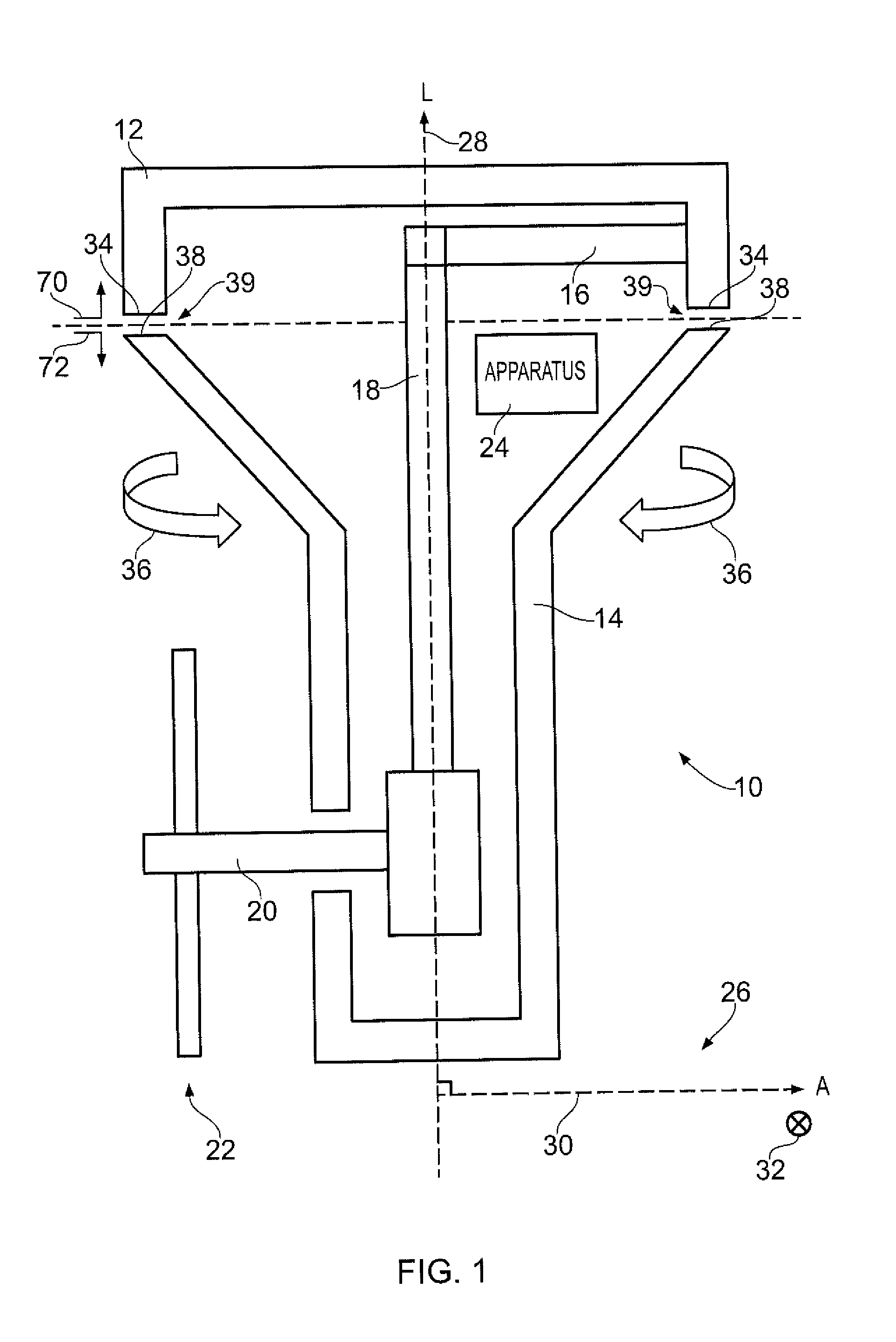
[0054]FIG. 1 illustrates a cross sectional side view of an azimuth thruster 10 according to various examples. The azimuth thruster 10 comprises an upper housing 12, a lower housing 14, an input shaft 16, a vertical shaft 18, a propeller shaft 20, a propeller 22, and apparatus 24. FIG. 1 also illustrates a cylindrical coordinate system 26 including a longitudinal axis 28, a polar axis 30 and an azimuth 32 that are orthogonal to one another.

[0055]The upper housing 12 of the azimuth thruster may be coupled to a hull of a vessel and may be stationary relative to the hull. The upper housing 12 houses the input shaft 16 and a part of the vertical shaft 18. The upper housing 12 includes a first surface 34 that defi...


PUM


Abstract

Apparatus to control transmission of data, the apparatus comprising: a controller configured to: receive data from at least a first sensor within an azimuth thruster; control storage of the received data in memory; determine whether at least one criterion is satisfied, the at least one criterion varying with the relative positioning of a first antenna mounted on a lower housing of the azimuth thruster and a second antenna mounted on an upper housing of the azimuth thruster, the lower housing being configured to rotate relative to the upper housing; and control transmission of the stored data from the first antenna in response to determining that the at least one criterion is satisfied.

Description

TECHNOLOGICAL FIELD[0001]The present disclosure concerns apparatus and methods for controlling transmission of data.BACKGROUND[0002]Mechanical systems may comprise at least one part that is rotatable relative to an adjacent (stationary or rotatable) part of the mechanical system. The transfer of electrical signals between two such parts may present several challenges due to the movement of the two parts.[0003]For example, a vessel may comprise an azimuth thruster for propelling the vessel in water. The azimuth thruster usually includes a propeller that may be rotated about a vertical axis to select the direction of thrust. Transferring an electrical signal between a stationary part of the azimuth thruster and a rotatable part of the azimuth thruster may present several challenges. By way of an example, it may be challenging to transfer an electrical signal via a wired connection between the stationary and rotatable parts because relative movement between the stationary and rotatable...

Claims


Application Information

Patent Timeline
Patent Type & Authority Applications(United States)
IPC IPC(8): H02J50/80H02J50/12H02J7/34B63H5/125
CPCH02J50/80B63H5/125H02J7/345H02J7/34H02J50/12B63H2025/028H02J7/00034H04B5/72H04B5/79H04B5/24B63H2005/1256
Inventor EDWARDS, HUW L.DHUTIA, VISHAL K.MITZALIS, FAIDONFRAU, EDOARDO G.BROMAN, MATHIAS H.SCHIFFERS, WERNER P.
Owner ROLLS ROYCE PLC
Learn More