

Thermally-responsive optical switching composites for thermal optical applications
- Summary
- Abstract
- Description
- Claims
- Application Information
AI Technical Summary
Benefits of technology
Problems solved by technology
Method used
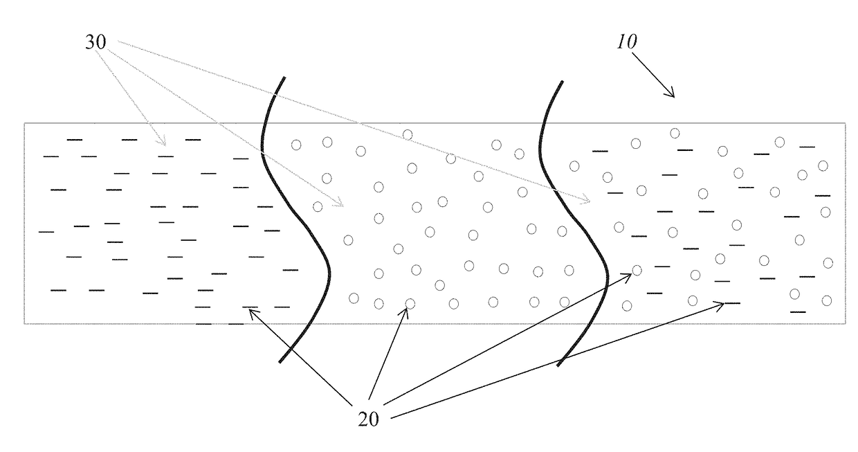
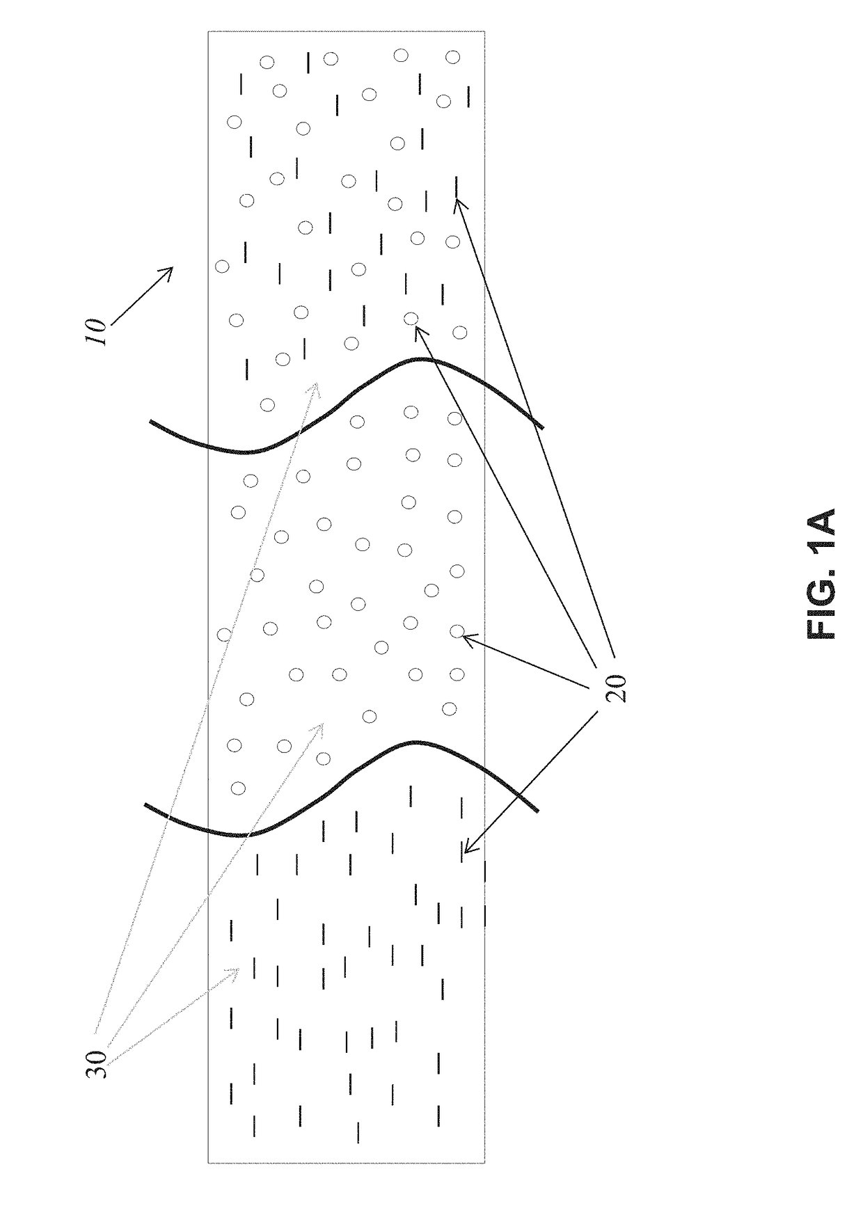
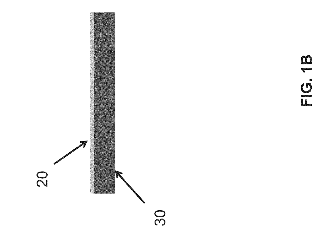
Image

Examples
example 1
[0048]Various composite films with different refractive indices were prepared using Gelest OE50 silicone as a matrix and RCF glass flake with different particle sizes as a filler material. Composite films were prepared as follows. Appropriate portions of silicone and filler were weighed out to make composites with 10, 20, 30, and 40 volume % filler in the silicone matrix as shown in FIG. 8. The silicone and glass filler were mixed in a planetary mixer for 5 minutes. The mixture was then placed under vacuum to remove remaining air bubbles in the mixture. Samples were then cast into aluminum molds and placed in an oven at 55° C. for 4 hours followed by 150° C. for 1 hour to cure. After curing, samples were removed from the aluminum die to make free standing films for analysis. Samples were cast nominally at 1 mm but also made with different thickness as shown in the table of FIG. 8.
example 2
[0049]In another set of experiments composite films with different refractive indices were prepared using Dow Corning OE-6550 silicone as a matrix and REF glass flake with different particle sizes as a filler material. Composite films were prepared as follows. Appropriate portions of silicone and filler were weighed out to make composites with 10, 20, 30, and 40 volume % filler in the silicone matrix as shown in FIG. 9. The silicone and glass filler was mixed in a planetary mixer for 5 minutes. The mixture was then placed under vacuum to remove remaining air bubbles in the mixture. Samples were then cast into aluminum molds and placed in an oven at 150° C. for 1 hour to cure the silicone. After curing, samples were removed from the aluminum die to make free standing films for analysis. Samples were cast nominally at 1 mm. Thermal and optical properties of resulting samples were then tested. The results are shown in FIG. 9.
example 3
[0050]Various composite films with different refractive indices were prepared using Dow Epoxy Resin331 as a matrix and RCF glass flake with different particle sizes as a filler material. Composite films were prepared as follows. Appropriate portions of silicone and filler were weighed out to make composites with 9, 18, 24, and 30 volume % filler in the epoxy matrix as shown in the table of FIG. 10. The epoxy and glass filler were mixed in a planetary mixer for 5 minutes. The mixture was then placed under vacuum to remove remaining air bubbles in the mixture. Samples were then cast into silicone molds and placed in an oven at 80° C. for 1 hour to cure the epoxy. After curing, samples were removed from the silicone die to make free standing films for analysis. Samples were cast nominally at 1 mm. Thermal and optical properties of resulting samples were then tested. Results are shown in FIG. 10.
[0051]FIG. 11 shows plots of the transmission curves for composites of the present invention...
PUM
| Property | Measurement | Unit |
|---|---|---|
| Fraction | aaaaa | aaaaa |
| Temperature | aaaaa | aaaaa |
| Volume | aaaaa | aaaaa |
Abstract
Description
Claims
Application Information