Travel control device for vehicle

Active Publication Date: 2017-02-09
TOYOTA JIDOSHA KK
View PDF3 Cites 10 Cited by
  • Summary
  • Abstract
  • Description
  • Claims
  • Application Information

AI Technical Summary

Benefits of technology

[0028]According to the above-mentioned aspect, even when the switch is in the non-engaged position, when the emergency avoidance steering is being carried out, the driving support controller is determined to be engaged. Thus, under the state

Problems solved by technology

However, there are the following problems in a related-art travel control device in which the electric power steering device is installed in the steering transmission system between the steered wheels and the steering transmission ratio variable device like the travel control device described in Japanese Patent Application Laid-open No. 2011-31770.
However, the electric power steering device is generating a steering torque so as to change the steering angle of the steered wheels, and thus the steering transmission ratio variable device cannot rotate the lower steering shaft, while

Method used


Image

  • Travel control device for vehicle
  • Travel control device for vehicle
  • Travel control device for vehicle

Examples


first embodiment

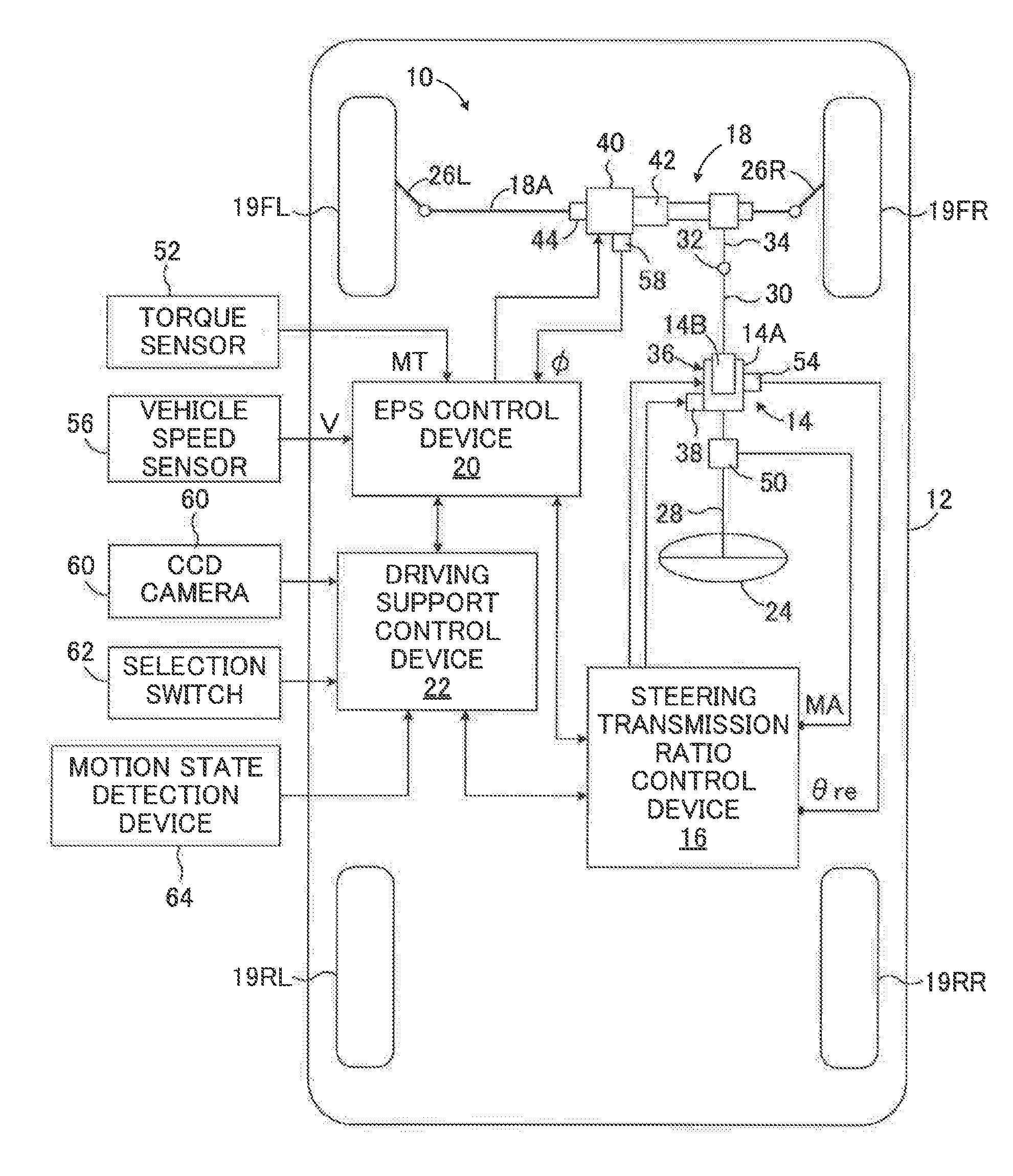
[0040]FIG. 1 is a schematic configuration diagram for illustrating a travel control device 10 according to a first embodiment of the present disclosure, which is installed in a vehicle 12. The travel control device 10 includes a steering transmission ratio variable device 14, a steering transmission ratio control device 16 configured to control the steering transmission ratio variable device 14, an electric power steering (EPS) device 18, an EPS control device 20 serving as a steering assist torque control device configured to control the electric power steering device 18, and a driving support control device 22. As illustrated in FIG. 1, the vehicle 12 includes front left and right wheels 19FL and 19FR, which are steered wheels, and rear left and right wheels 19RL and 19RR, which are non-steered wheels. The front left and right wheels 19FL and 19FR are steered via a rack bar 18A and tie rods 26L and 26R by the electric power steering device 18 driven in response to an operation by ...

second embodiment

[0091]FIG. 5 is a flowchart for illustrating a steering transmission ratio control routine of a travel control device for a vehicle according to a second embodiment of the present disclosure. In FIG. 5, the same steps as those step illustrated in FIG. 2 are denoted by the same step number as that assigned in FIG. 2. The same applies to FIG. 6 and FIG. 7 referred to later.

[0092]In the second embodiment, the steering assist torque control and the driving support control that are carried out respectively by the EPS control device 20 and the driving support control device 22 are carried out in accordance with the flowcharts illustrated in FIG. 3 and FIG. 4, respectively, as in the case of the first embodiment described above. The same applies to third and fourth embodiments of the present disclosure described later.

[0093]As appreciated from a comparison between FIG. 5 and FIG. 2, Step 110 to Step 130, Step 210, and Step 290 are carried out in the same way as the corresponding steps of t...

third embodiment

[0101]FIG. 6 is a flowchart for illustrating a steering transmission ratio control routine of a travel control device for a vehicle according to a third embodiment of the present disclosure.

[0102]As appreciated from a comparison between FIG. 6 and FIG. 2, also in the third embodiment, Step 110 to Step 130, Step 210, and Step 290 are carried out in the same way as the corresponding steps of the first embodiment. Step 10 is carried out prior to Step 110, and when Step 130 is completed, the steering transmission ratio control proceeds to Step 210.

[0103]In Step S10, it is determined whether or not the driving support control is being carried out by the driving support control device 22 in the same way as in the case of Step 140 of the first embodiment. When a negative determination is made, the steering transmission ratio control proceeds to Step 110. When an affirmative determination is made, the steering transmission ratio control proceeds to Step S20. When the negative determination ...


PUM


Abstract

A travel control device for vehicle (10) includes a steering transmission ratio variable device (14), a steering transmission ratio control device (16) configured to carry out such control that an actual relative rotational angle (θre) of the steering transmission ratio variable device reaches a target value (θret), a power steering device (18), a steering assist torque control device (20) configured to control the power steering device, and a driving support device (22) configured to correct a target steering assist torque so that an actual steering angle of steered wheels (19FL, 19FR) reaches a target steering angle for driving support. When the driving support device is in operation (Step 140), the magnitude of a change in a relative rotational angle generated by the control of the steering transmission ratio variable device is decreased (Step 150 to 200) compared to a case in which the driving support device is not in operation.

Description

CROSS-REFERENCE TO RELATED APPLICATIONS[0001]The disclosure of Japanese Patent Application No. JP 2015-157655 filed on Aug. 7, 2015 is incorporated herein by reference in its entirety.BACKGROUND[0002]1. Technical Field[0003]The present disclosure relates to a travel control device for a vehicle including a steering transmission ratio variable device and a power steering device.[0004]2. Description of the Related Art[0005]As a travel control device for vehicles such as a motor vehicle, there has hitherto been well known a travel control device including a steering transmission ratio variable device and an electric power steering device in a steering transmission system between a steering wheel and steered wheels. The steering transmission ratio variable device is arranged between an upper steering shaft and a lower steering shaft, and is configured to rotate the lower steering shaft with respect to the upper steering shaft, thereby changing a steering transmission ratio. This type of...

Claims


Application Information

Patent Timeline
IPC IPC(8): B62D6/00B62D6/06B62D5/04B62D5/00
CPCB62D6/002B62D5/008B62D5/0472B62D5/0463B62D6/06B62D6/007B62D15/025
Inventor KOJO, TAKAHIRO
Owner TOYOTA JIDOSHA KK
Why Eureka
Try Eureka