
Double seat valve

Active Publication Date: 2017-02-09
EVOGUARD GMBH
View PDF6 Cites 6 Cited by
  • Summary
  • Abstract
  • Description
  • Claims
  • Application Information

AI Technical Summary

Benefits of technology

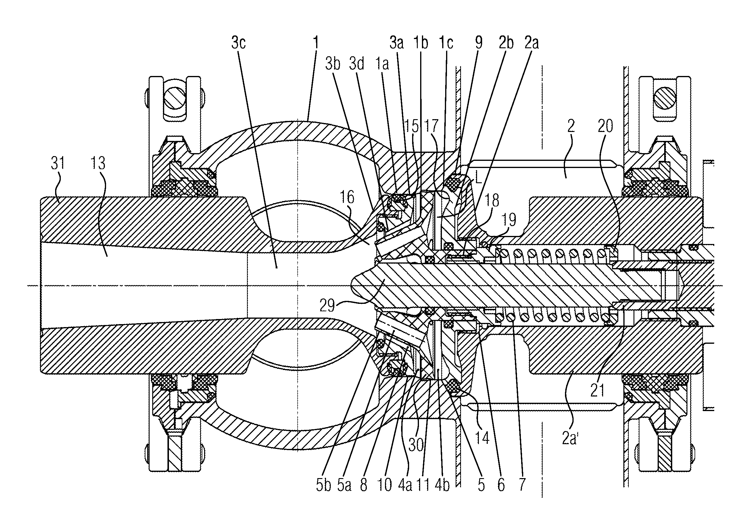
The invention relates to a double seat valve that prevents cleaning agents from leaking on the sealing valve disc while there is a negative pressure on the seal. It includes a concave and rounded guide fin which guides the side flow and ensures flawless inflow conditions into the first channels. The guide fin leads the side flow that passes through the leakage gap in the lower lift position to the center of the upper part of the leakage room and past the sealing seal of the upper valve disc. This design allows for complete cleaning of the leakage room.

Problems solved by technology

Thereby, there is the risk of leakages on the seals.
Effective cleaning in the area of the radial seal of the deflector is made difficult, even if the radial seal of the deflector performs hauling axial movements along the wall of the leakage room.
In each lift position, radial sealing contact between the deflector and the wall of the leakage room is ensured, which makes flawless cleaning of this area difficult.

Method used


Image

  • Double seat valve
  • Double seat valve
  • Double seat valve

Examples


Embodiment Construction

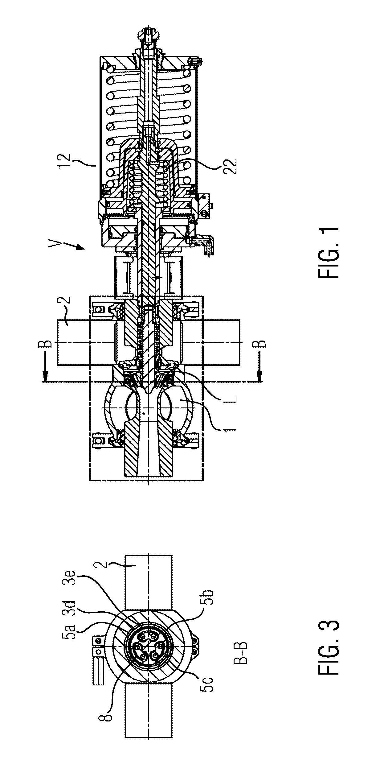
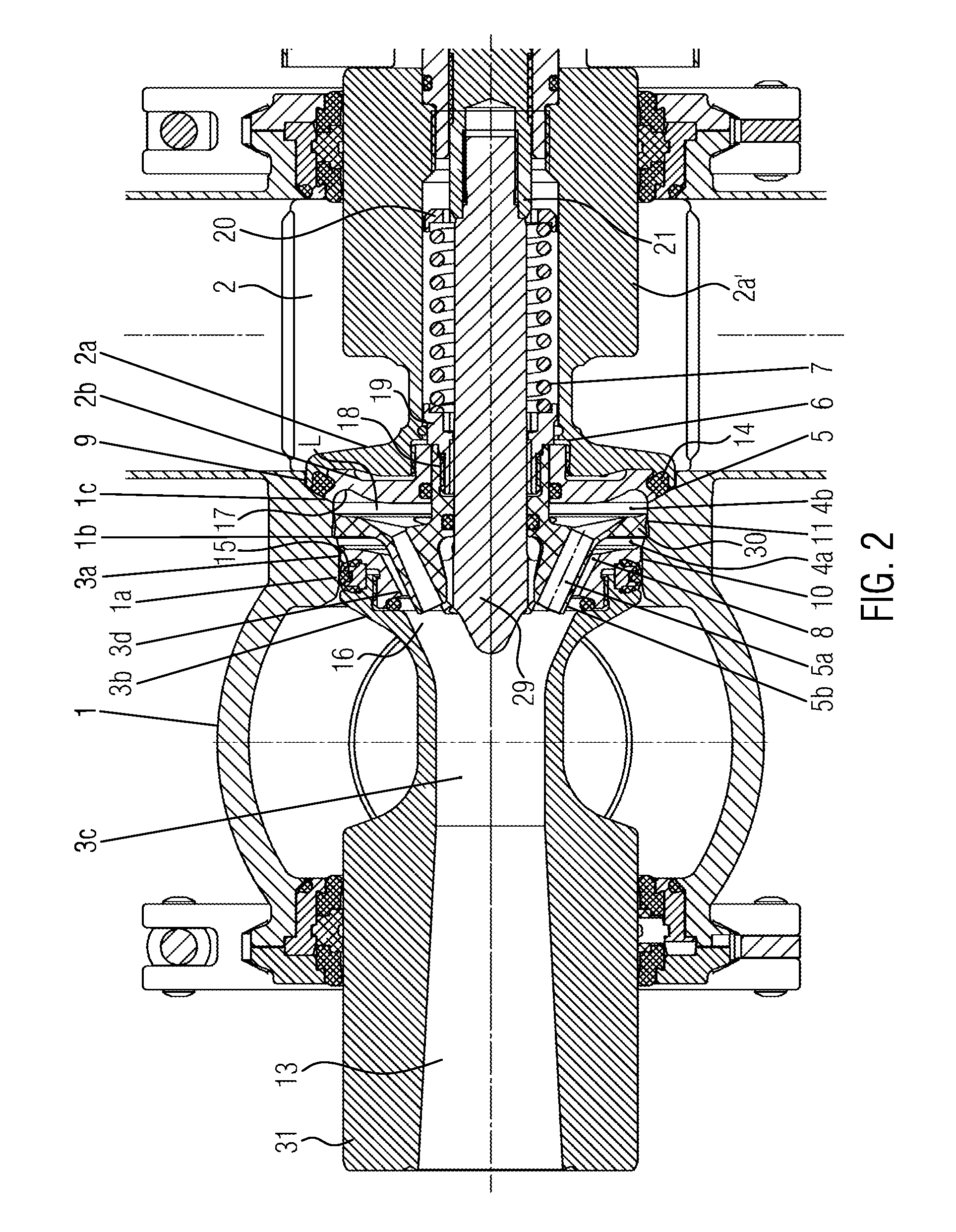
[0052]A double seat valve V in a closing or locking position shown in FIGS. 1 to 3 is used for selective separation or connection of media or product lines 1, 2 (first and second pipes) in a leakage room L and for example connecting pieces for the valve housings that bear the product lines 1, 2. The double seat valve V is operated for example by means of a pneumatic drive 12 that contains several pistons and springs as well as a passive spring 22 in this case (FIG. 1).

[0053]A two-piece upper valve disc 2a, 2b (first closing component) is connected to the drive 12 through a drive pipe 2a′ and contains a seal 14, here an axial seal, to interact with a seat 1c (first closing component seat) in the valve housing. The seat 1c is a cone area that comes in contact with a cylindrical section 17 in the direction towards a deflecting shoulder 1b on the external wall of the leakage room L. From the deflecting shoulder 1b, an essentially cylindrical seat 1a (second closing component seat) exten...


PUM


Abstract

In a double seat valve with upper and lower valve discs and a flow divider in a leakage room, wherein respectively one valve disc can be set to a lift position to supplying a cleaning medium flow into the leakage room, and first channels are provided in the flow divider and second channels in the lower valve disc towards a leakage outlet, the first channels are disposed in extensions of the flow divider that axially bridge the lower leakage room part and that join within the second channels the flow divider forming in at least one of two lift positions with its external circumference with the external wall of the leakage room a leakage gap for a side flow that is significantly smaller than a main flow that is deflected and directed by the flow divider into the first channels or into the second channels and to the leakage outlet.

Description

CROSS-REFERENCE TO RELATED APPLICATION[0001]The present application claims priority to German Application No. DE 102015215089.5. The priority application, DE 102015215089.5, is hereby incorporated by reference.FIELD OF THE DISCLOSURE[0002]The invention relates to a double seat valve.BACKGROUND[0003]In the double seat valve known from JP 57-154564A, the first channels join a disc-like deflector in the lower part of the leakage room and in alignment to the second channels in the lower valve disc. On the outer circumference, the deflector has a radial seal that interacts with the internal wall of the leakage room in the statistical state and also during axial movements of the deflector. The deflector is charged in the direction towards the lower valve disc through the spring that supports itself on the upper valve disc. In the upper lift position, the cleaning medium that flows in under pressure is led through a circumferential throttle gap before it flows through the first channels. O...

Claims


Application Information

Patent Timeline
IPC IPC(8): F16K1/44
CPCF16K1/44F16K1/446Y10T137/88038
Inventor SAUER, MARTIN
Owner EVOGUARD GMBH
Learn More