Display device, electronic device, and system

a technology for electronic devices and displays, applied in the field of display devices, can solve the problems of enlargement of display regions that might entail a reduction in portability, and the portability of display and portability is difficult to improve, so as to achieve the effect of extending the display region of an electronic device, and being highly portabl

Inactive Publication Date: 2017-02-09
SEMICON ENERGY LAB CO LTD
View PDF8 Cites 46 Cited by
  • Summary
  • Abstract
  • Description
  • Claims
  • Application Information

AI Technical Summary

Benefits of technology

[0033]According to one embodiment of the present invention, a display region of an electronic device can be enlarged. A display region of an electronic device can be protected. A function of selecting the size of a display region of an electronic device depending on its intended use can be provided. A display device for extending a display region of an electronic device can be provided. A highly portable electronic device can be provided.
[0034]Power consumption of an electronic device can be reduced. An electronic device with high visibility independent of the intensity of external light can be provided.

Problems solved by technology

However, in applications of portable devices and the like, an enlargement of display regions might entail a reduction in portability.
For this reason, browsability of display and portability are difficult to improve at the same time.

Method used


Image

  • Display device, electronic device, and system
  • Display device, electronic device, and system
  • Display device, electronic device, and system

Examples


embodiment 1

[0079]In this embodiment, structural examples of a display device, an electronic device, and a system of one embodiment of the present invention are described.

Structural Example 1

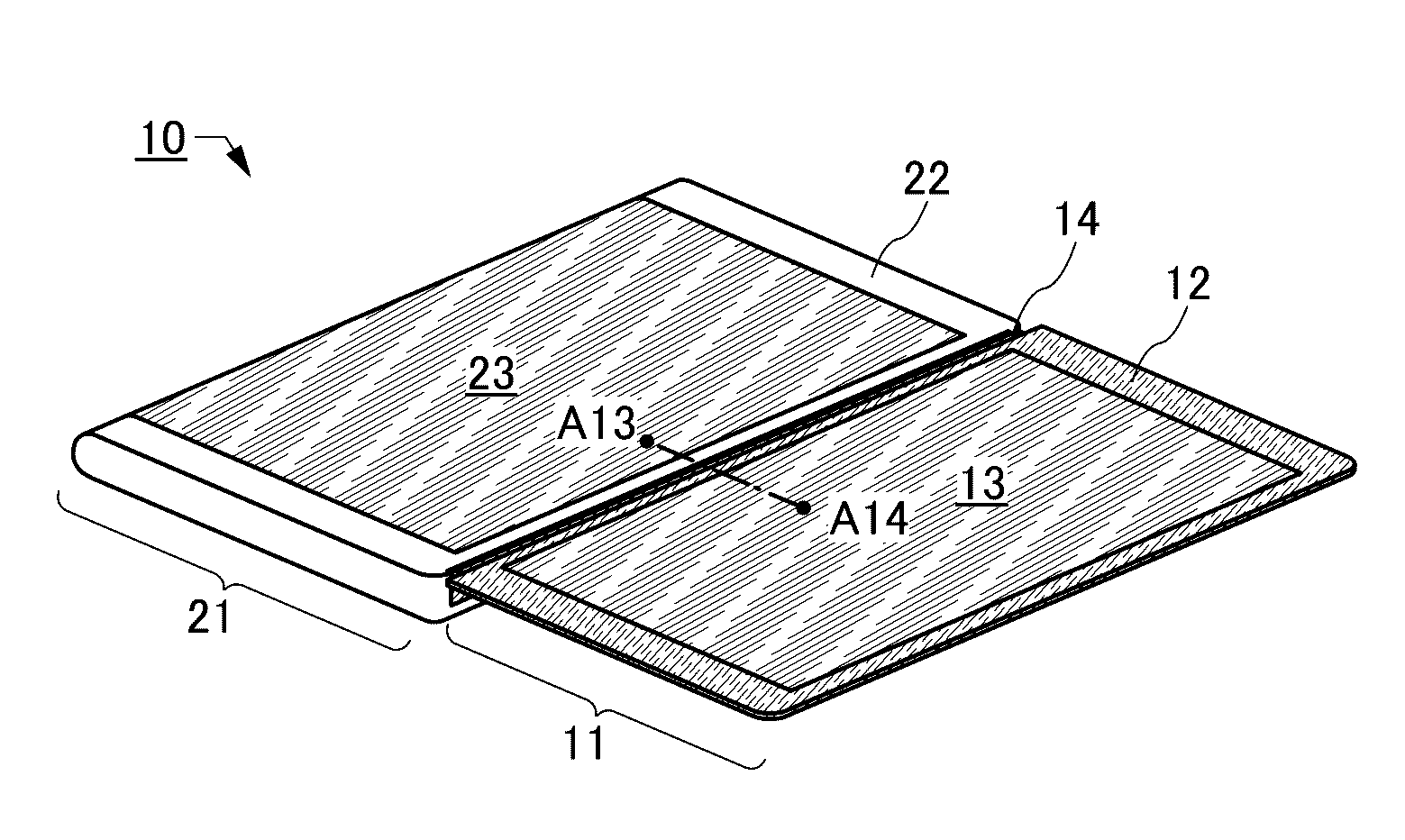
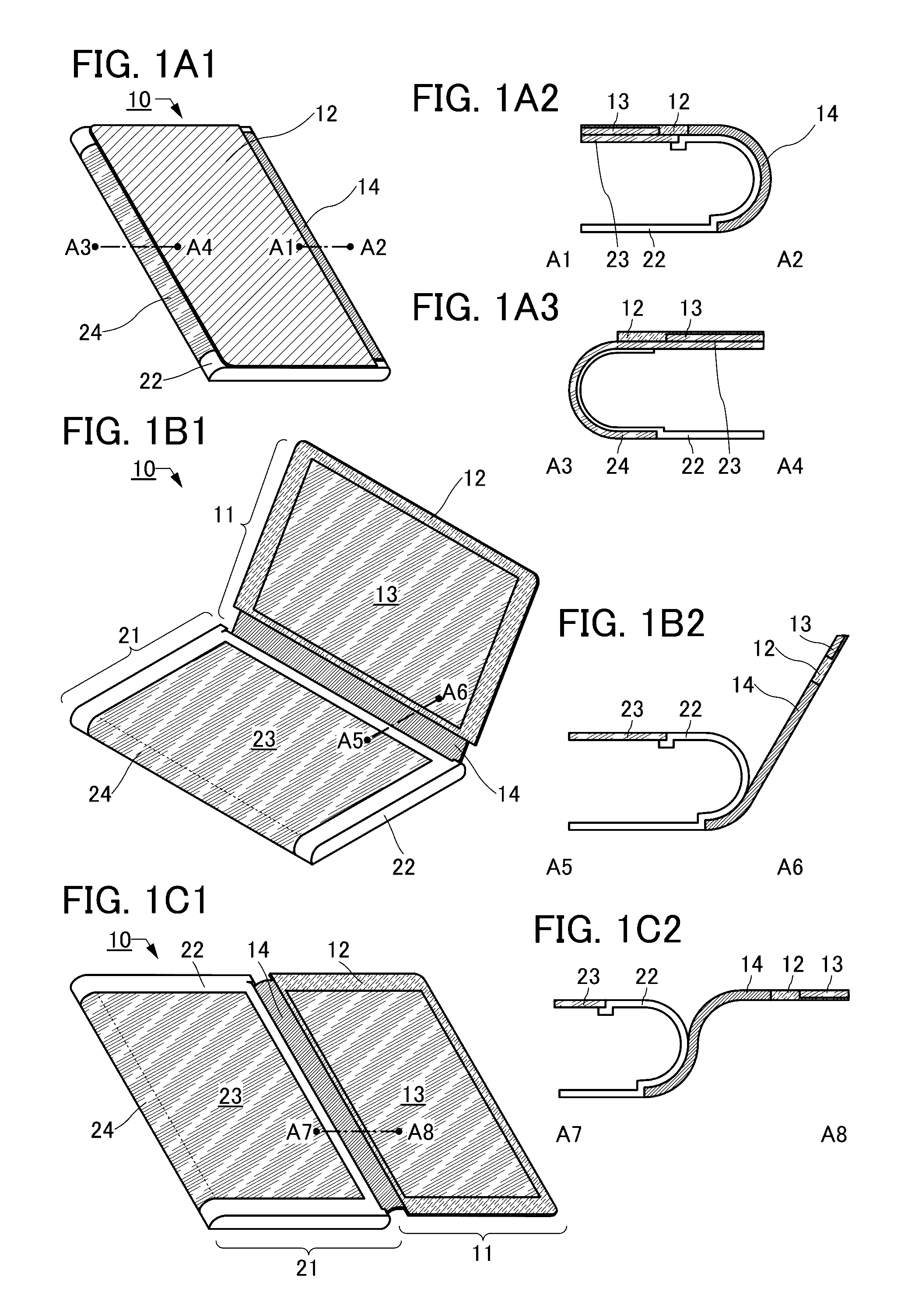
[0080]FIGS. 1A1, 1B1, and 1C1 are perspective schematic views of a system 10 including a display device 11 and an electronic device 21. FIG. 1A1 illustrates a state in which the display device 11 and the electronic device 21 overlap with each other (this state is also referred to as a closed state or a folded state). FIG. 1B1 illustrates a state in which they are unfolded (this state is also referred to as an opened state). FIG. 1C1 illustrates a state in which they are further unfolded (opened) to be substantially parallel to each other.

[0081]FIGS. 1A2 and 1A3 are cross-sectional schematic views taken along the section lines A1-A2 and A3-A4, respectively, in FIG. 1A1. FIG. 1B2 is a cross-sectional schematic view taken along the section line A5-A6 in FIG. 1B1. FIG. 1C2 is a cross-sectional schematic view ta...

example 2

Structural Example 2

[0127]A structural example partly different from Structural example 1 described above will be described below. Note that description of the portions already described is omitted and different portions are described.

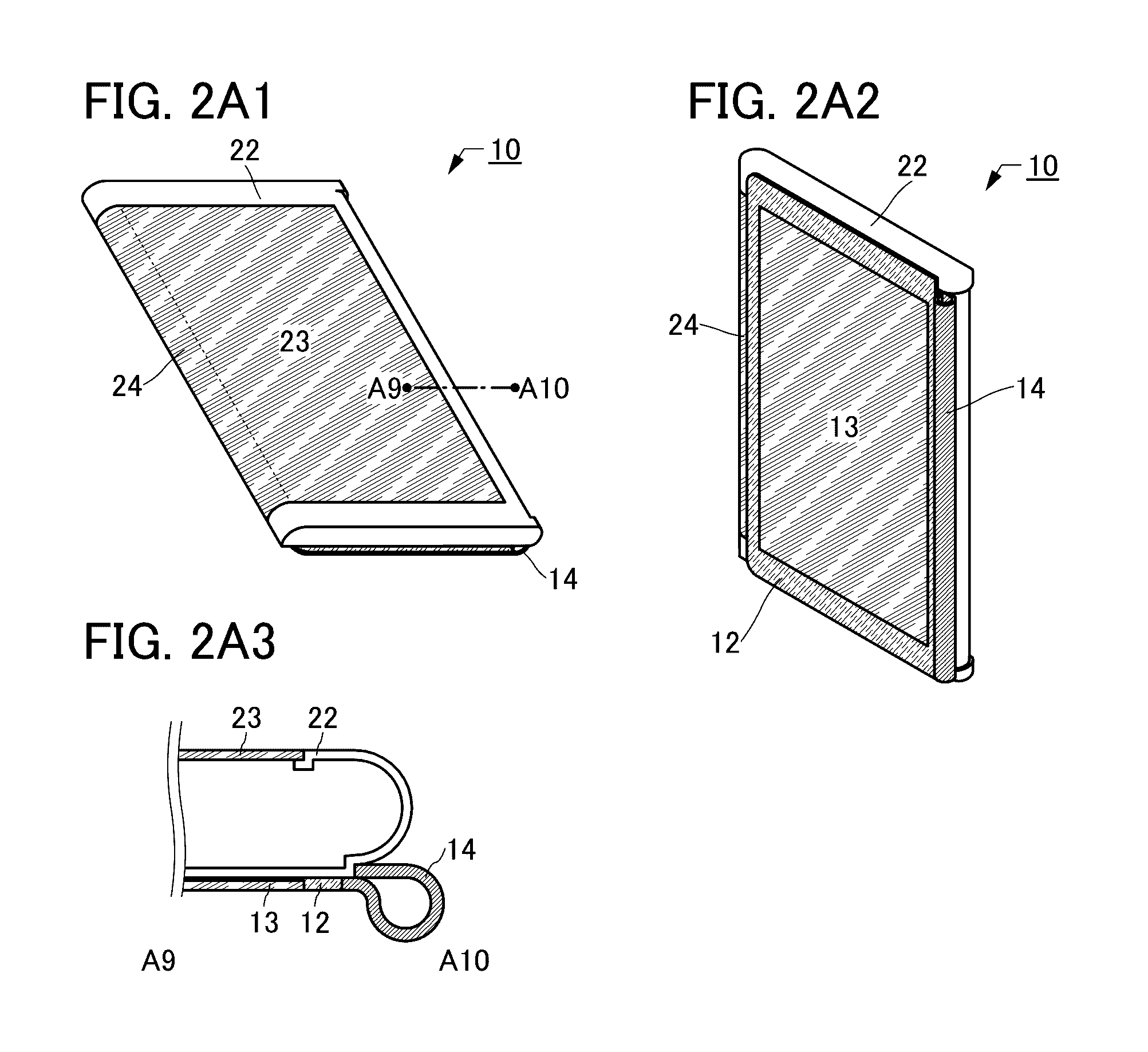
[0128]FIGS. 5A1, 5A2, 5B, and 5C are perspective schematic views of a system 10 described as an example below. The system 10 illustrated in FIGS. 5A1 to 5C differs from that in Structural example 1 mainly in including a support mechanism 25.

[0129]FIGS. 5A1 and 5A2 illustrate a state in which the housing 22 and the support 12 are closed. FIG. 5A1 illustrates the support 12 side, and FIG. 5A2 illustrates the back surface side of the housing 22.

[0130]The housing 22 includes the support mechanism 25. As illustrated in FIGS. 5A1 and 5A2, the support mechanism 25 is preferably stored in the housing 22 when not in use. For example, a portion of a surface of the housing 22 and a portion of a surface of the support mechanism 25 are made to be positioned on the ...

example 3

Structural Example 3

[0136]A structural example partly different from the above structural examples will be described below. Note that description of the portions already described is omitted and different portions are described.

[0137]FIGS. 7A to 7C are perspective schematic views of a system 10 described as an example below. The system 10 illustrated in FIGS. 7A to 7C differs from those described above mainly in the structure of the connection portion 14.

[0138]FIG. 7A illustrates a state in which the housing 22 and the support 12 are closed. FIG. 7B illustrates a state in which they are opened. FIG. 7C illustrates a state in which the electronic device 21 and the display device 11 are separated from each other.

[0139]The connection portion 14 of the display device 11 illustrated in FIGS. 7A to 7C includes a movable portion 14a and a detachment portion 14b.

[0140]The movable portion 14a has a function of connecting the detachment portion 14b and the support 12 to each other. The movab...


PUM

PropertyMeasurementUnit
thicknessaaaaaaaaaa
sizesaaaaaaaaaa
sizesaaaaaaaaaa

Abstract

A system includes an electronic device and a display device. The electronic device includes a first display portion positioned on a first surface including an upper surface of a housing and a second display portion positioned on a second surface including a first side surface of the housing. The display device includes a third display portion positioned on a third surface of a support portion and a connection portion having a function of connecting to the housing and reversibly changing the relative positions of the support portion and the housing between a first configuration and a second configuration. In the first configuration, the support portion covers the first display portion such that the second display portion is visible. In the second configuration, the support portion and the housing are opened such that the first, second, and third display portions are visible.

Description

BACKGROUND OF THE INVENTION[0001]1. Field of the Invention[0002]One embodiment of the present invention relates to a display device. One embodiment of the present invention relates to an electronic device. One embodiment of the present invention relates to a system including a display device.[0003]Note that one embodiment of the present invention is not limited to the above technical field. Examples of the technical field of one embodiment of the present invention disclosed in this specification include a semiconductor device, a display device, a light-emitting device, a power storage device, a memory device, an electronic device, a lighting device, an input device, an input / output device, a method for driving any of them, and a method for manufacturing any of them.[0004]2. Description of the Related Art[0005]Electronic devices including display devices have recently been diversified. Examples of the electronic devices include cellular phones, smartphones, tablet terminals, and wear...

Claims


Application Information

Patent Timeline
Patent Type & Authority Applications(United States)
IPC IPC(8): G02F1/1335G02F1/1333G06F1/16
CPCG02F1/133555G06F1/1616G02F1/133308G06F1/1654G06F1/1681G06F1/1647G02F1/13338
Inventor YAMAZAKI, SHUNPEI
Owner SEMICON ENERGY LAB CO LTD
Why Eureka
Try Eureka