Article Transport Facility

a technology for transporting facilities and articles, applied in the direction of transportation and packaging, storage devices, etc., can solve the problems of difficult simultaneous transfer of articles to/from two storage sections, inability to simultaneously store articles to two storage sections with a single stacker crane, etc., and achieve the effect of convenient simultaneous transfer of articles and efficient transport of articles

Active Publication Date: 2017-03-02
DAIFUKU CO LTD
View PDF3 Cites 20 Cited by
  • Summary
  • Abstract
  • Description
  • Claims
  • Application Information

AI Technical Summary

Benefits of technology

[0010]In this way, since the first elevator body and the second elevator body are able to individually move up/down, the two storage sections to/from which articles are transferred by the first transferring device and the second transferring device are not limited to those in the same row,

Problems solved by technology

However, with the stacker crane disclosed in Patent Document 1, although it is possible to simultaneously transfer articles to/from two storage sections with a single stacker crane, the two storage sections to/from which articles can be transferred are limited to two storage sections that are in the same row and adjacent to each other in the rack width direction.
Therefore, in the case of storing articles to storage sections for example, unless empty storage sections in which no

Method used


Image

  • Article Transport Facility
  • Article Transport Facility
  • Article Transport Facility

Examples


first embodiment

[0056]The following describes a first embodiment of an article transport facility with reference to the drawings.

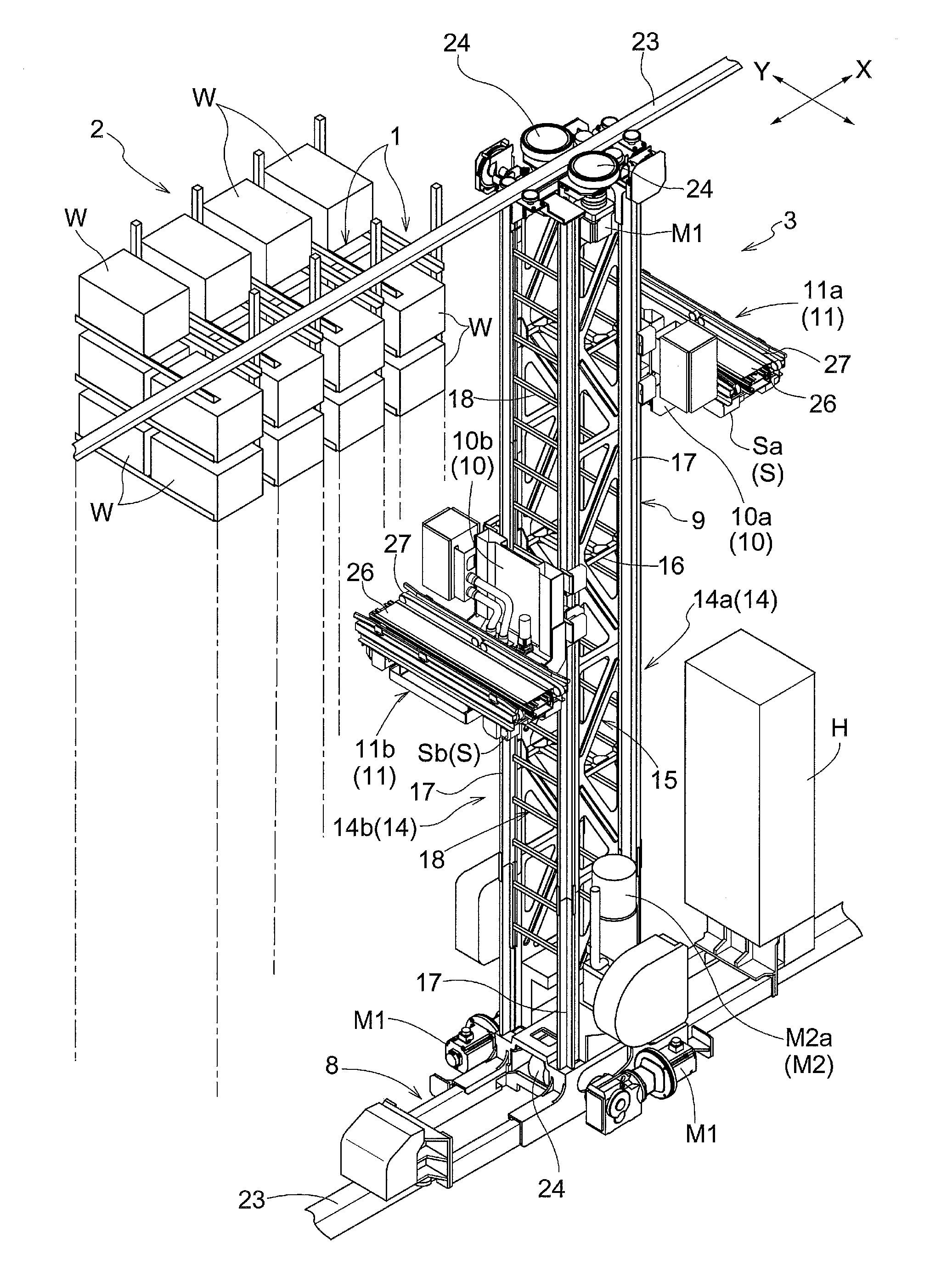
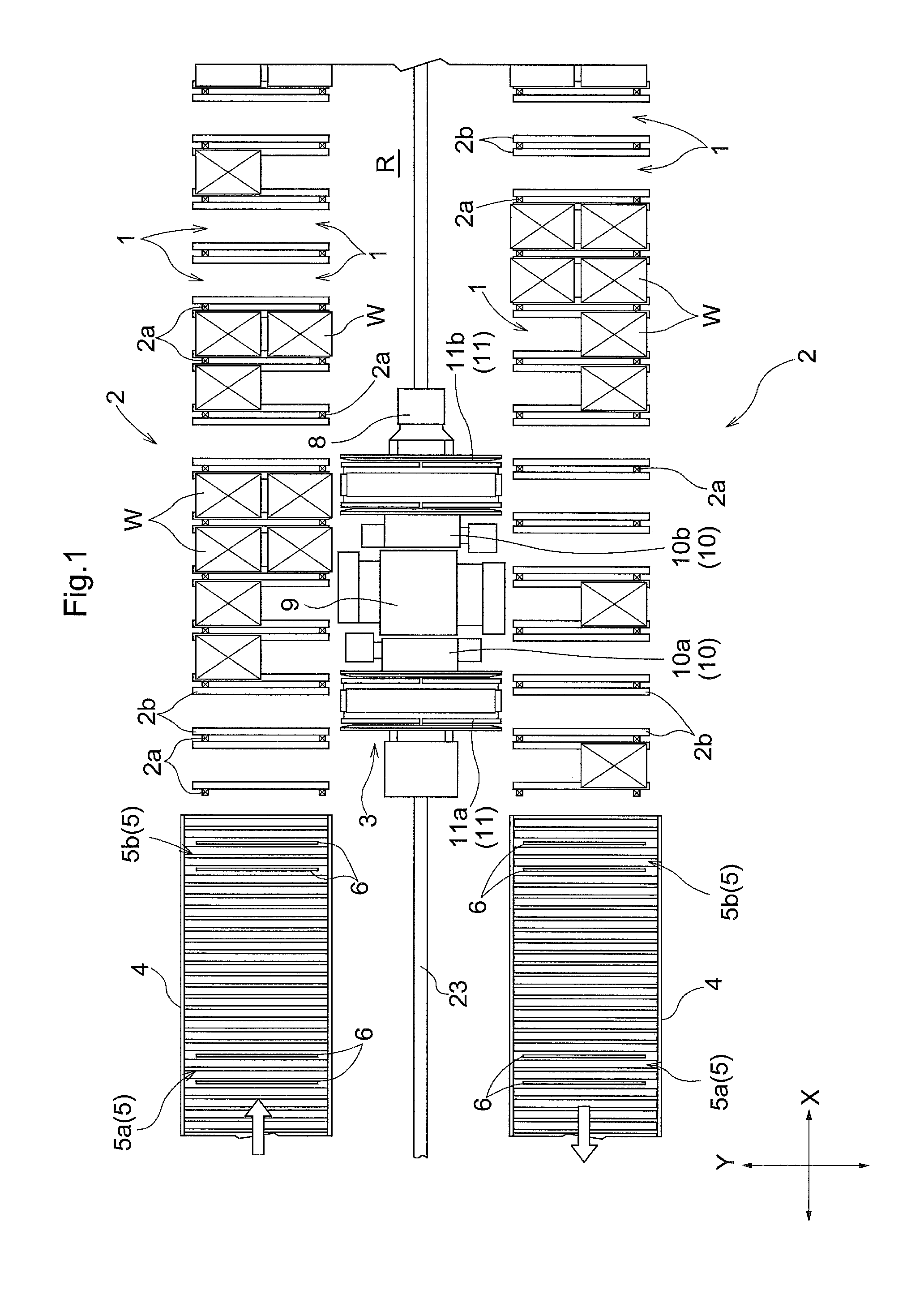
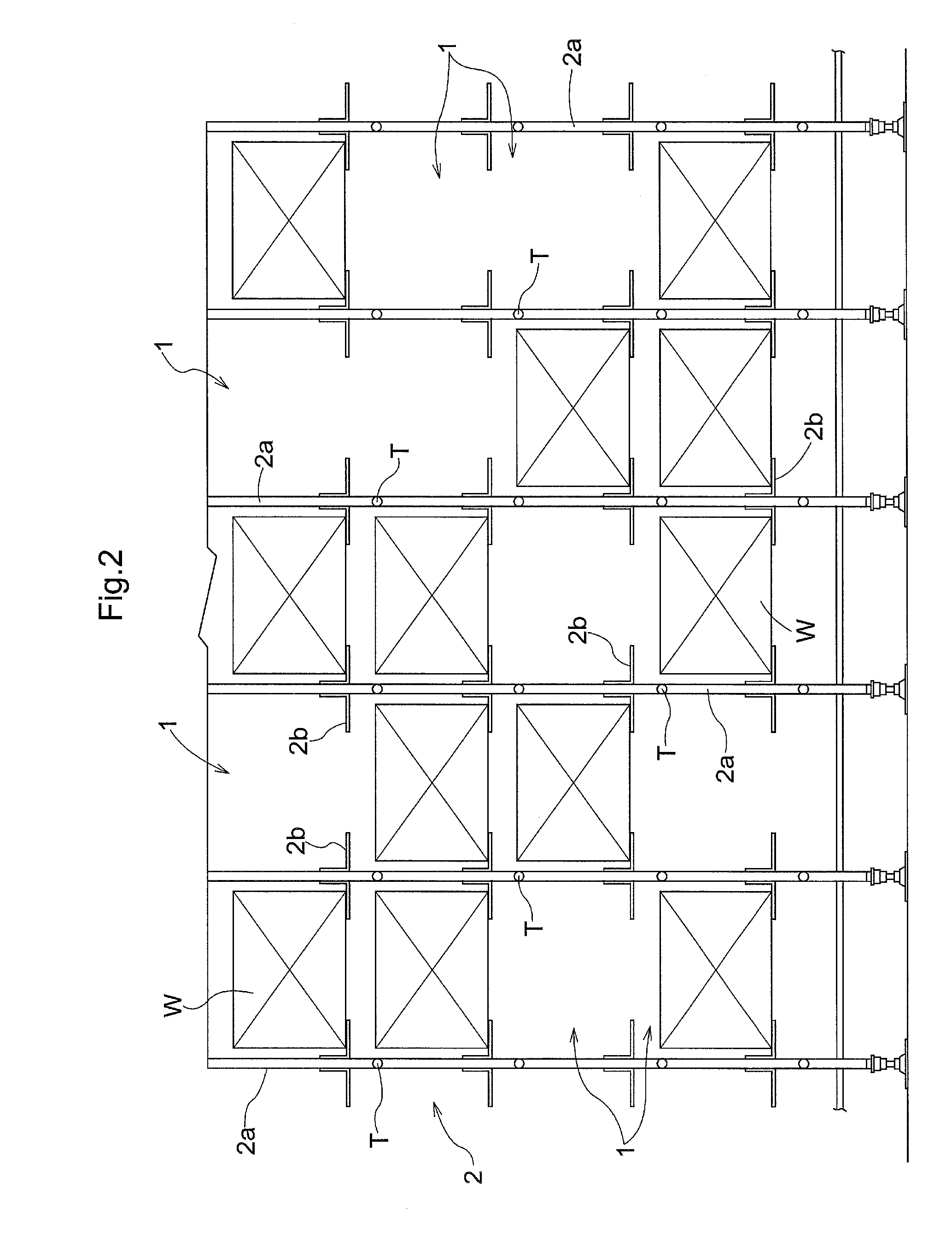
[0057]As shown in FIG. 1, the article transport facility is configured with: article storage racks 2 that are each provided with a plurality of storage sections 1 for storing articles W; and a stacker crane 3 that travels in front of the article storage racks 2 along a travel path R in the rack width direction, and transports articles W between transferring sections 5 of transport conveyors 4 and the plurality of storage sections 1, and between the plurality of storage sections 1.

[0058]Note that, in FIG. 1, the direction in which the plurality of storage sections 1 are aligned in each article storage rack 2 is defined as “rack width direction”, and the direction that is orthogonal to the rack width direction in plan view is defined as “rack front-rear direction”. The direction indicated by an arrow X is the rack width direction (the longitudinal direction of the path), an...

second embodiment

[0226]Next, a description is given of a second embodiment of an article transport facility with reference to the drawings.

[0227]Note that in the description of the second embodiment, mainly the movement control that is different from that in the first embodiment is described, and the description of the same configuration as that in the first embodiment is omitted.

[0228]As shown in FIG. 15, in the movement control, the target travel stopping position is set such that the elevation guide mast 9 is located in the center between the first target storage section 1a and the second target storage section 1b in the rack width direction based on the travel distance information corresponding to the first target storage section 1a and the travel distance information corresponding to the second target storage section 1b, and the operations of the travelling motor M1 are controlled (travel control) so that the travelling carriage 8 is caused to travel to the target travel stopping position.

[0229...

third embodiment

[0237]Next, a description is given of a third embodiment of an article transport facility with reference to the drawings.

[0238]Note that in the description of the third embodiment, mainly the configurations of the transferring devices 11 that are different from those in the first embodiment are described, and the description of the same configuration as that in the first embodiment is omitted.

[0239]As shown in FIG. 17 to FIG. 19, the first transferring device 11a includes: a moving platform 51 that is supported so as to be able to slide along the rack width direction relative to the first elevator body 10a; a moving motor (not shown in the drawings) that causes the moving platform 51 to slide along the rack width direction relative to the first elevator body 10a; a pair of clamp fork devices 52 that are supported so as to be able to slide along the rack width direction relative to the moving platform 51 and that are able to protrude and retract along the rack front-rear direction; a...


PUM


Abstract

A stacker crane is provided with: a travelling carriage that is configured to be able to travel along the rack width direction; a first mast that is provided so as to stand on the travelling carriage; a second mast that is provided so as to stand on the same travelling carriage on which the first mast is provided; a first elevator body that is configured to be guided along the first mast; a second elevator body that is configured to be guided along the second mast so as to be able to move up/down independently of the first elevator body, and that is aligned with the first elevator body in the rack width direction in plan view; a first transferring device that is supported by the first elevator body; and a second transferring device that is supported by the second elevator body.

Description

CROSS-REFERENCE TO RELATED APPLICATION[0001]This application claims priority to Japanese Patent Application No. 2015-168160 filed Aug. 27, 2015, the disclosure of which is hereby incorporated in its entirety by reference.FIELD OF THE INVENTION[0002]The present invention relates to an article transport facility that includes: an article storage rack in which a plurality of storage sections are arranged in a plurality of rows in the vertical direction and a plurality of columns in the rack width direction; and a stacker crane that travels in front of the article storage rack along the rack width direction.BACKGROUND[0003]An example of the article transport facility above is disclosed in JP H9-315518A (Patent Document 1). In the article transport facility according to Patent Document 1, the stacker crane includes: a travelling carriage that is able to travel in the rack width direction; an elevator body that is guided along a mast that is provided so as to stand on the travelling carri...

Claims


Application Information

Patent Timeline
IPC IPC(8): B65G1/137B65G1/04
CPCB65G1/1373B65G1/0407B65G1/0421B65G1/0428B65G1/1375
Inventor UEDA, YUICHIIWATA, MASASHIGEMAKIMURA, KAZUNORI
Owner DAIFUKU CO LTD
Why Eureka
Try Eureka