Blower

a technology of blower and discharge flow rate, which is applied in the direction of pump components, positive displacement liquid engines, liquid fuel engine components, etc., can solve the problems of low power consumption and high discharge flow rate of blower of recent years, and achieve high discharge flow rate, low power consumption, and increase power consumption

Active Publication Date: 2017-03-02
MURATA MFG CO LTD
View PDF4 Cites 11 Cited by
  • Summary
  • Abstract
  • Description
  • Claims
  • Application Information

AI Technical Summary

Benefits of technology

[0007]However, blowers of recent years tend to have low power consumption and high discharge flow rate. Therefore, there is a demand for blowers whose discharge flow rate is made considerably higher than that of the pump in Patent Document 1 without increasing power consumption.
[0008]Accordingly, it is an object of the present disclosure to provide a blower whose discharge flow rate per power consumption can be considerably increased.

Problems solved by technology

However, blowers of recent years tend to have low power consumption and high discharge flow rate.

Method used


Image

  • Blower
  • Blower
  • Blower

Examples


Embodiment Construction

Embodiment of the Present Disclosure

[0050]The piezoelectric blower 100 according to an embodiment of the present disclosure is described below.

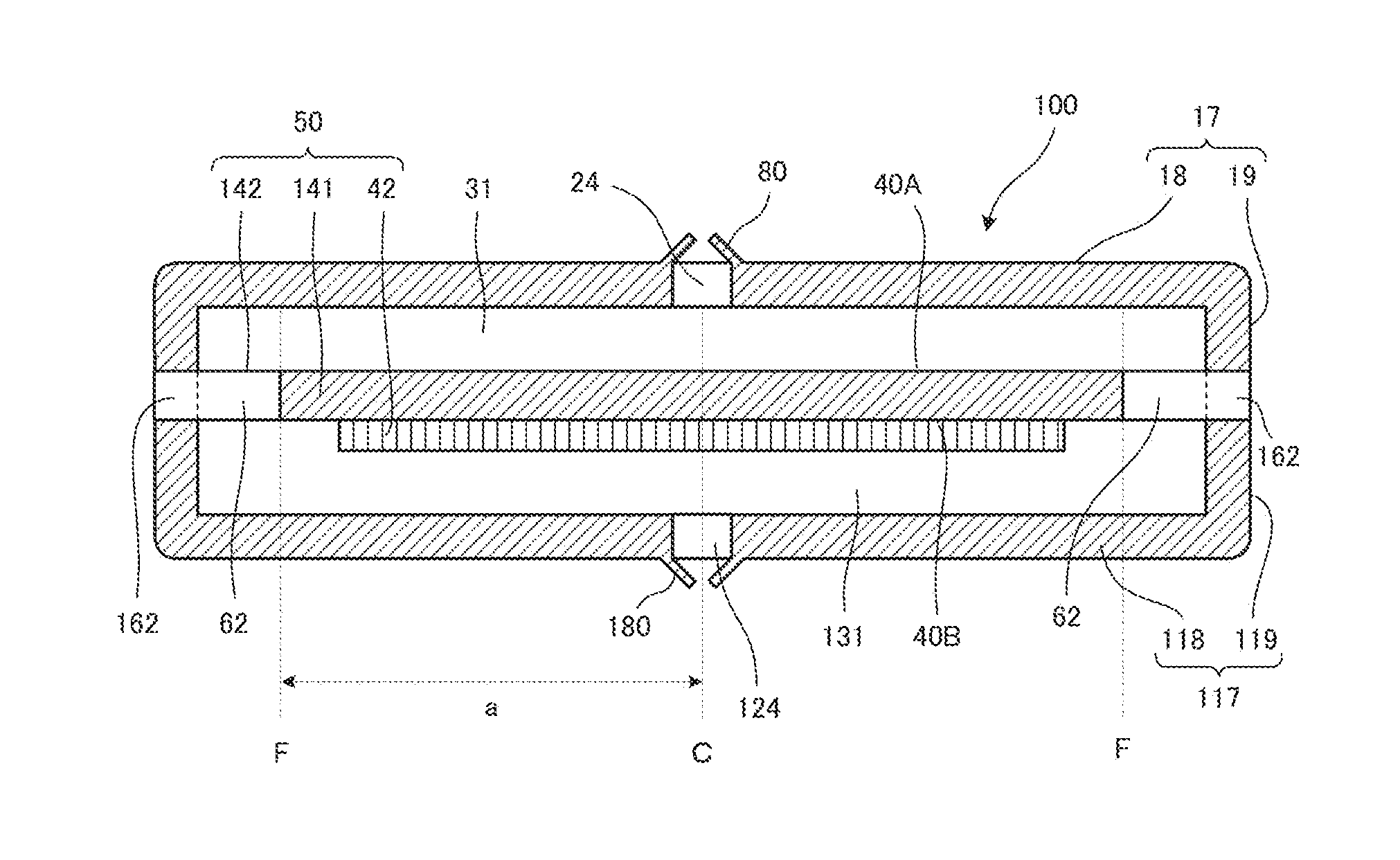
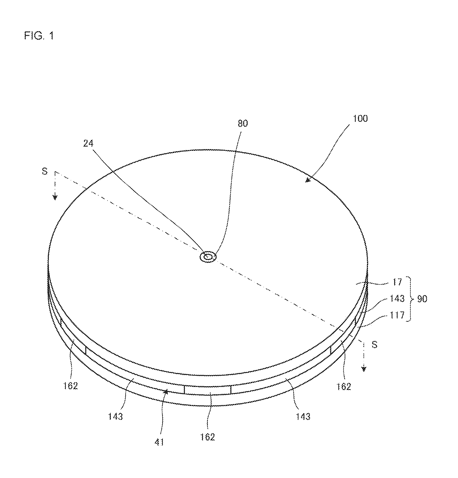
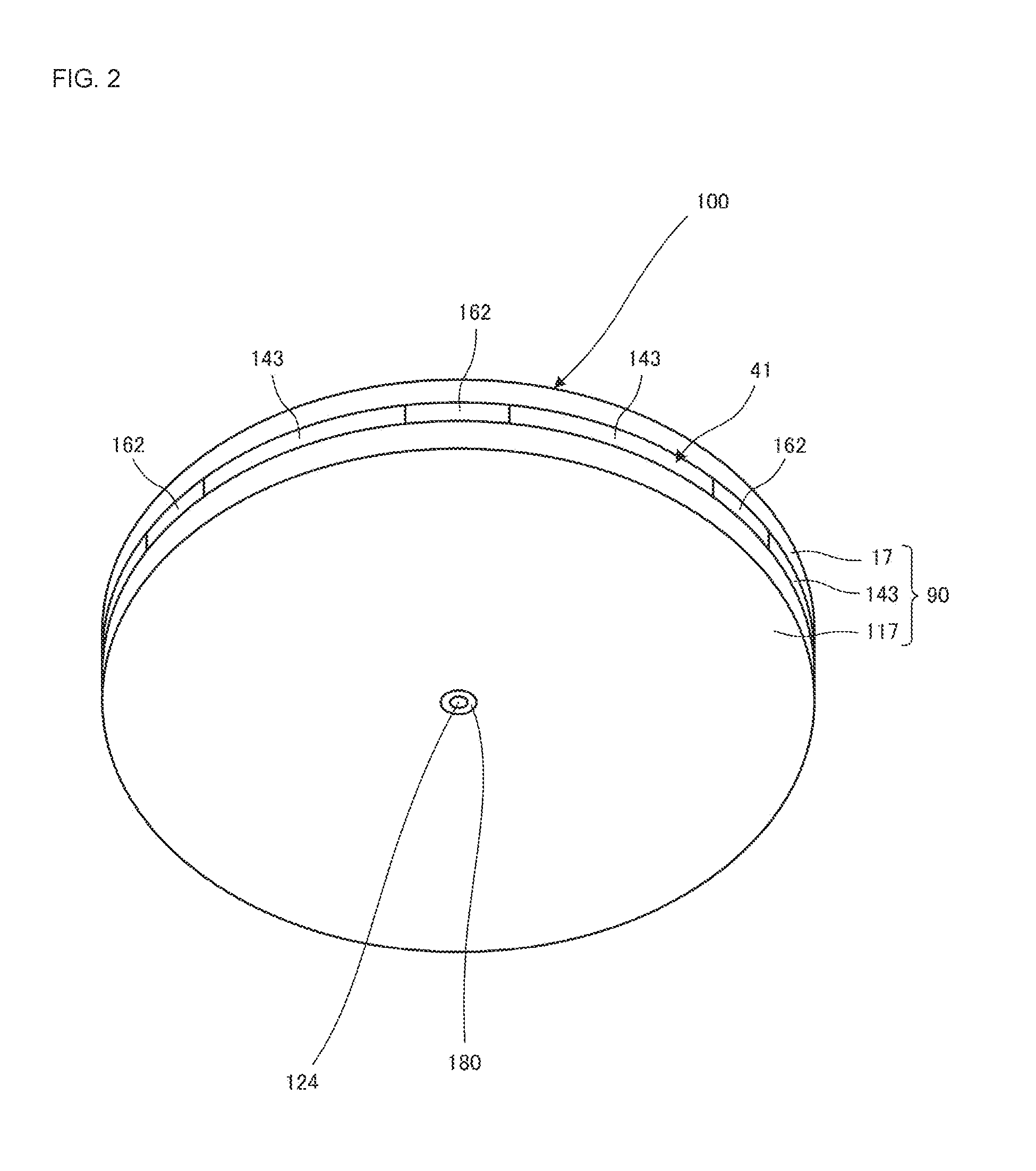
[0051]FIG. 1 is an external perspective view of the piezoelectric blower 100 according to the embodiment of the present disclosure. FIG. 2 is an external perspective view of the piezoelectric blower 100 shown in FIG. 1. FIG. 3 is a plan view of the vibrating plate 41 shown in FIG. 1. FIG. 4 is a sectional view taken along line S-S of the piezoelectric blower 100 shown in FIG. 1.

[0052]The piezoelectric blower 100 includes a first valve 80, the first housing 17, the vibrating plate 41, a piezoelectric element 42, a second housing 117, and a second valve 180 in that order from the top, and has a structure in which these components are successively placed upon each other.

[0053]The vibrating plate 41 is disc-shaped, and is made of, for example, stainless steel (SUS). The thickness of the vibrating plate 41 is 0.6 mm. The vibrating plate 41 include...


PUM


Abstract

A piezoelectric blower includes a first valve, a first housing, a vibrating plate, a piezoelectric element, a second housing, and a second valve. The first housing forms, together with the vibrating plate, a first blower chamber. A first top plate portion includes a first vent hole that allows an inside of the first blower chamber to communicate with an outside of the first blower chamber. The second housing forms, together with an actuator, a second blower chamber. A second top plate portion includes a second vent hole that allows an inside of the second blower chamber to communicate with an outside of the second blower chamber. The vibrating plate includes an opening portion and a third vent hole, the opening portion allowing an outer periphery of the first blower chamber and an outer periphery of the second blower chamber to communicate with each other.

Description

[0001]This is a continuation of International Application No. PCT / JP2015 / 060439 filed on Apr. 2, 2015 which claims priority from Japanese Patent Application No. 2014-104226 filed on May 20, 2014. The contents of these applications are incorporated herein by reference in their entireties.FIELD OF THE DISCLOSURE[0002]The present disclosure relates to a blower that transports gas.DESCRIPTION OF THE RELATED ART[0003]Hitherto, various types of blowers that transport gas have been known. For example, Patent Document 1 discloses a piezoelectric driven type pump.[0004]The pump includes a piezoelectric disc, a disc to which the piezoelectric disc is joined, and a body that, together with the disc, forms a cavity. The body has an inlet into which a fluid flows and an outlet from which the fluid flows out. The inlet is provided between a central axis of the cavity and an outer periphery of the cavity. The outlet is provided at the central axis of the cavity.[0005]In the pump described in Paten...

Claims


Application Information

Patent Timeline
Patent Type & Authority Applications(United States)
IPC IPC(8): F04B45/047F04B53/10F04B45/04
CPCF04B45/047F04B53/10F04B45/041F04B39/121F04B39/123F04B43/0054F04B43/023F04B43/046F04B53/16
Inventor TANAKA, NOBUHIRAKURIHARA, KIYOSHI
Owner MURATA MFG CO LTD
Why Eureka
Try Eureka