
Automotive headlamp module

a headlamp module and headlamp technology, applied in the direction of fixed installation, transportation and packaging, light and heating equipment, etc., can solve the problems of high price, high cost, and high implementation difficulty of common low-cost vehicles, and achieve reduced cost and component costs, enhanced safety during vehicle operation, and sufficient visual range

Active Publication Date: 2017-03-02
HYUNDAI MOTOR CO LTD
View PDF1 Cites 3 Cited by
  • Summary
  • Abstract
  • Description
  • Claims
  • Application Information

AI Technical Summary

Benefits of technology

This patent describes an automotive headlamp module that is designed to be cost-effective and can be used in low-cost vehicles. The module has beam patterns for low-beam, high-beam, and ADB modes, and uses a common DC motor for rotating the shield. The use of a DC motor reduces costs and allows for application in vehicles with a lower budget. The module also ensures a sufficient visual range for the driver and provides safety during operation of the vehicle. Additionally, it allows for a fail-safe function in case of a breakdown in the high-beam or ADB modes. Overall, this patent provides a cost-effective solution for improving safety and visual range in automotive headlamps.

Problems solved by technology

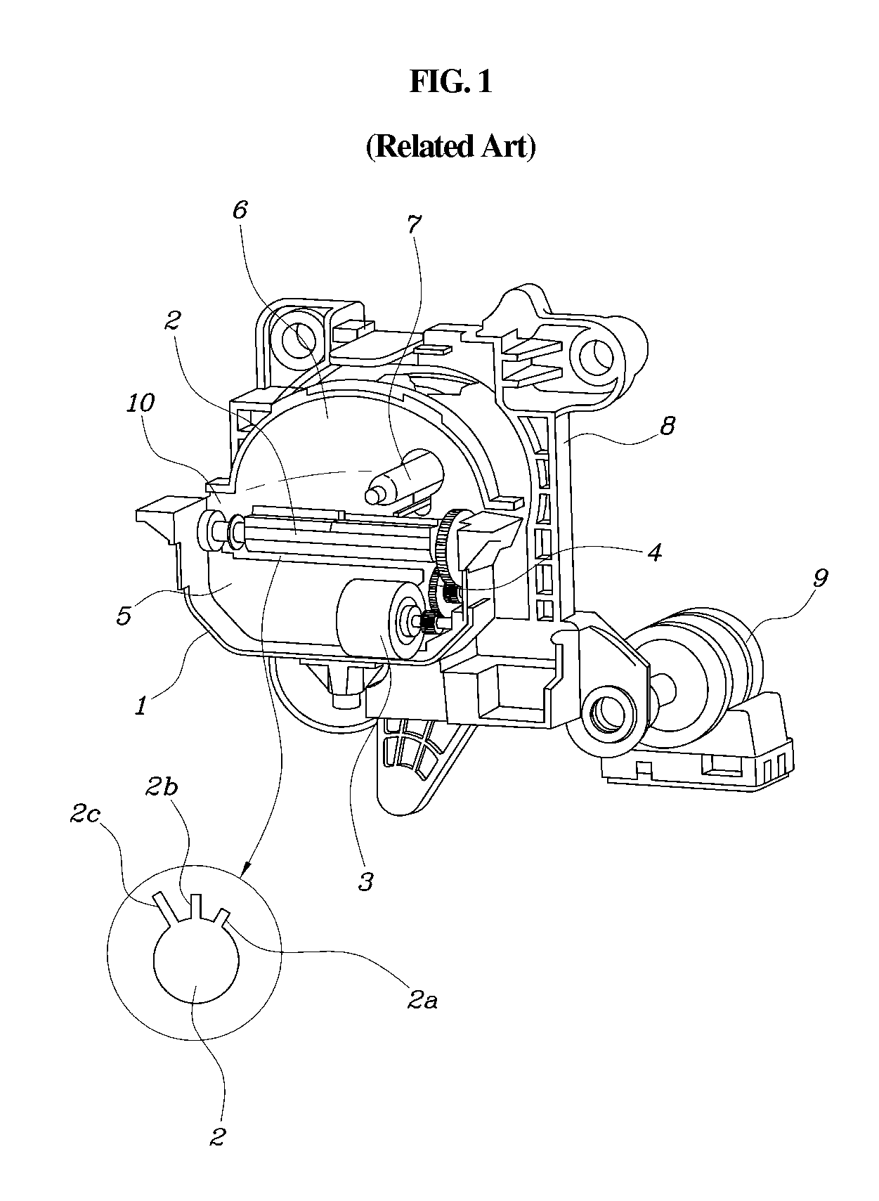
The shield motor 3, is not a common direct current (e.g., DC) motor, but a stepping motor, that accurately adjusts a rotational angle of the shield 2, but has a disadvantage of high price.
Moreover, a specific sensor 10 to detect a rotational position and a complex control logic is required, thereby making implementation difficult in common low-cost vehicles.
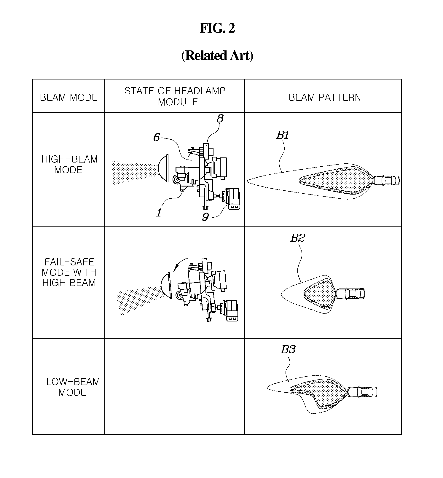
For example, when a problem occurs with the shield motor 3 or the headlamp, the driver of an approaching vehicle may have their field of vision impacted thus potentially contributing to an accident.
Additionally, performance deteriorates compared to a low beam state, thereby reducing safety during operation of the vehicle.

Method used


Image

  • Automotive headlamp module
  • Automotive headlamp module
  • Automotive headlamp module

Examples


Embodiment Construction

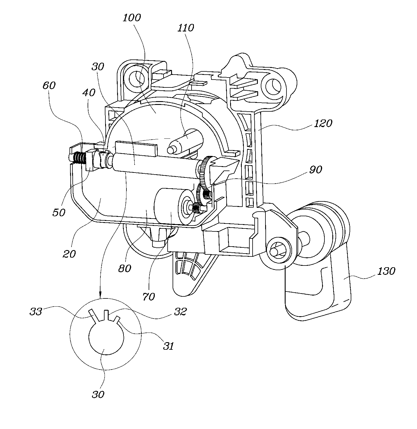
[0038]An automotive headlamp module according to exemplary embodiments of the present invention is described hereafter in detail with reference to the accompanying drawings. In the following detailed description, only certain exemplary embodiments of the present invention have been shown and described, simply by way of illustration. As those skilled in the art would realize, the described exemplary embodiments may be modified in various different ways, all without departing from the spirit or scope of the present invention. Accordingly, the drawings and description are to be regarded as illustrative in nature and not restrictive. Like reference numerals designate like elements throughout the specification.

[0039]The terminology used herein is for the purpose of describing particular embodiments only and is not intended to be limiting of the invention. As used herein, the singular forms “a”, “an” and “the” are intended to include the plural forms as well, unless the context clearly in...


PUM


Abstract

An automotive headlamp module that reduces manufacturing cost and increases availability for low-cost vehicles is provided. The automotive headlamp provides a rotational force to a shield via a DC motor and improves safety during operation by implementing a beam pattern in a low-beam mode when performing a fail-safe function due to breakdown in a high-beam mode or an ADB mode. In particular, the automotive headlamp includes a drum type shield rotatably disposed with respect to a shield housing and has a high-beam protrusion, a low-beam protrusion, and an adaptive driving-beam (ADB) protrusion on an exterior side and a shield disc coupled to the shield that rotates. A housing disc guide is movable in a longitudinal direction of the shield by the shield housing and has an end in contact with the shield disc and a return spring and presses a housing disc to the shield disc with accumulated elastic force.

Description

CROSS REFERENCE TO RELATED APPLICATION[0001]The present application claims priority to Korean Patent Application No. 10-2015-0121779, fried Aug. 28, 2015, the entire contents of which is incorporated herein for all purposes by this reference.BACKGROUND[0002]Field of the Invention[0003]The present invention relates to an automotive headlamp module and, more particularly, to a module used at a low cost by simplifying components thereof and that implements a beam pattern in a low-beam mode when a fail-safe function is performed due to breakdown in a high-beam mode or an adaptive driving-beam mode.[0004]Description of the Related Art[0005]Generally, beam patterns formed by automotive headlamp modules are classified into a low-beam mode, a high-beam mode, and an adaptive driving-beam (e.g., ADB) mode. For example, the ADB mode, automatically adjusts the direction and angle of light based on the driving conditions, and is a technology that automatically adjusts into a high-beam mode and a...

Claims


Application Information

Patent Timeline
IPC IPC(8): F21S8/10B60Q1/14
CPCF21S48/1794F21S48/145F21S48/142F21S48/1305B60Q1/1438F21S41/695F21V17/162F21W2107/00F21S41/43F21S41/47F21S41/698F21S41/435F21S41/683
Inventor SHIN, JIK SOOJIN, KEON SOONA, JIN HOLEE, KI HONGAHN, BYOUNG SUK
Owner HYUNDAI MOTOR CO LTD
Learn More