Communication device

a communication device and communication technology, applied in the direction of trunk circuits, current supply arrangements, transmission, etc., can solve the problems of degrading the communication quality of the communication device, and achieve the effect of improving the communication quality

Inactive Publication Date: 2017-03-02
OKI DATA CORP
View PDF25 Cites 1 Cited by
  • Summary
  • Abstract
  • Description
  • Claims
  • Application Information

AI Technical Summary

Benefits of technology

[0008]With this configuration, communication quality can be improved.

Problems solved by technology

However, the communication quality of a communication device may be degraded.

Method used


Image

  • Communication device
  • Communication device
  • Communication device

Examples


first embodiment

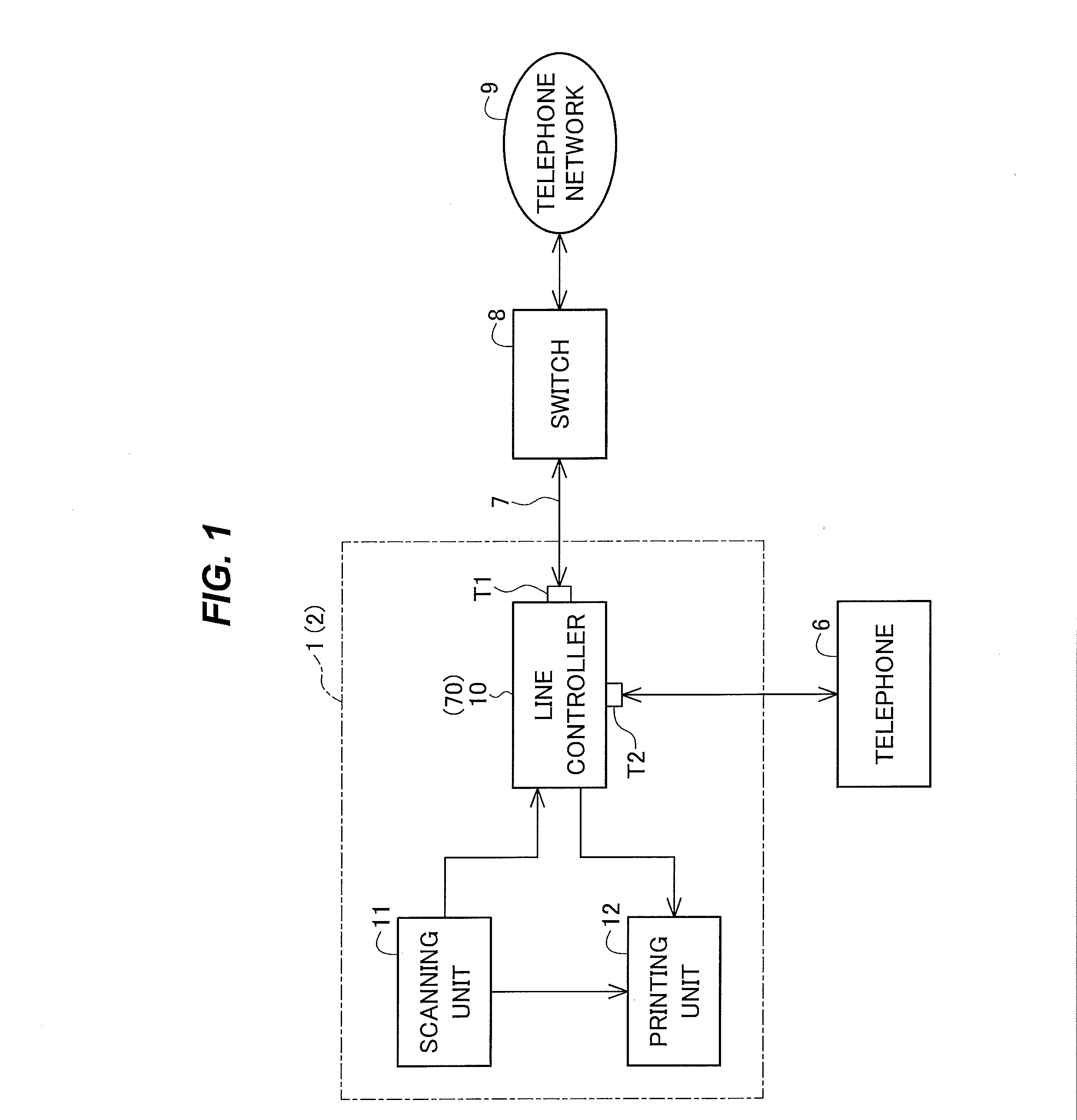
[0025]FIG. 1 illustrates an exemplary configuration of a communication device 1 according to a first embodiment of the present invention. The communication device 1 is a multi-function peripheral (MFP) having functions, such as copying, facsimile, and scanning. The communication device 1 includes a scanning unit (or scanner) 11, printing unit (or printer) 12, and a line controller 10.

[0026]The scanning unit 11 reads information, such as characters or graphics, printed on, for example, a document to generate image data. Further, when the communication device 1 functions as a copier, the scanning unit 11 supplies the generated image data to the printing unit 12; when the communication device 1 functions as a facsimile machine, the scanning unit 11 supplies the generated image data to the line controller 10.

[0027]The printing unit 12 prints image data supplied from the scanning unit 11 or line controller 10 on a recording medium, such as a paper sheet.

[0028]The line controller 10 contr...

second embodiment

[0115]A communication device 2 according to a second embodiment will now be described. This embodiment causes the switch 8 to stop transmission of the dial tone signal before performing the operation for determining the terminal impedance. Parts that are substantially the same as those of the communication device 1 according to the first embodiment have the same reference characters, and descriptions thereof will be omitted appropriately.

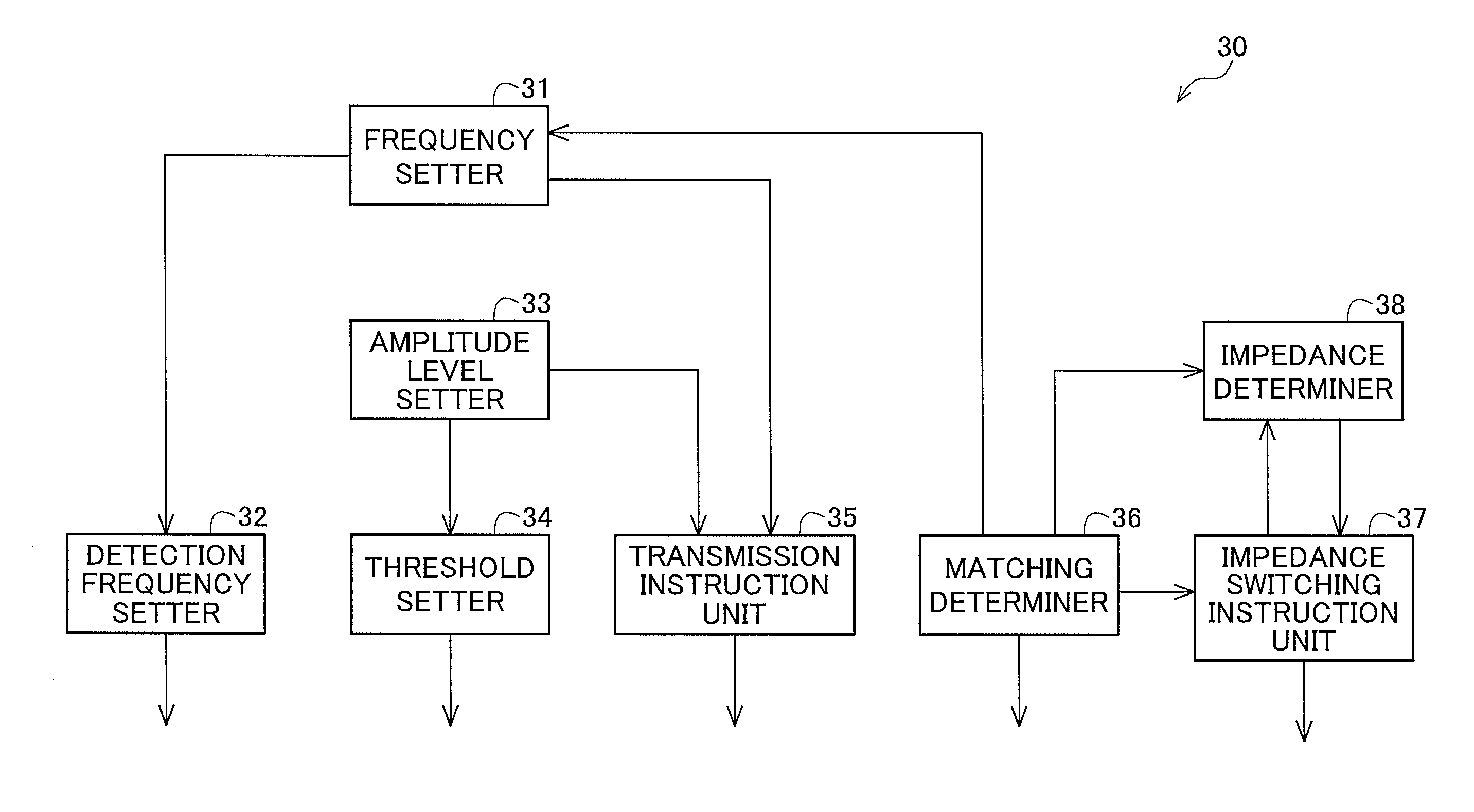
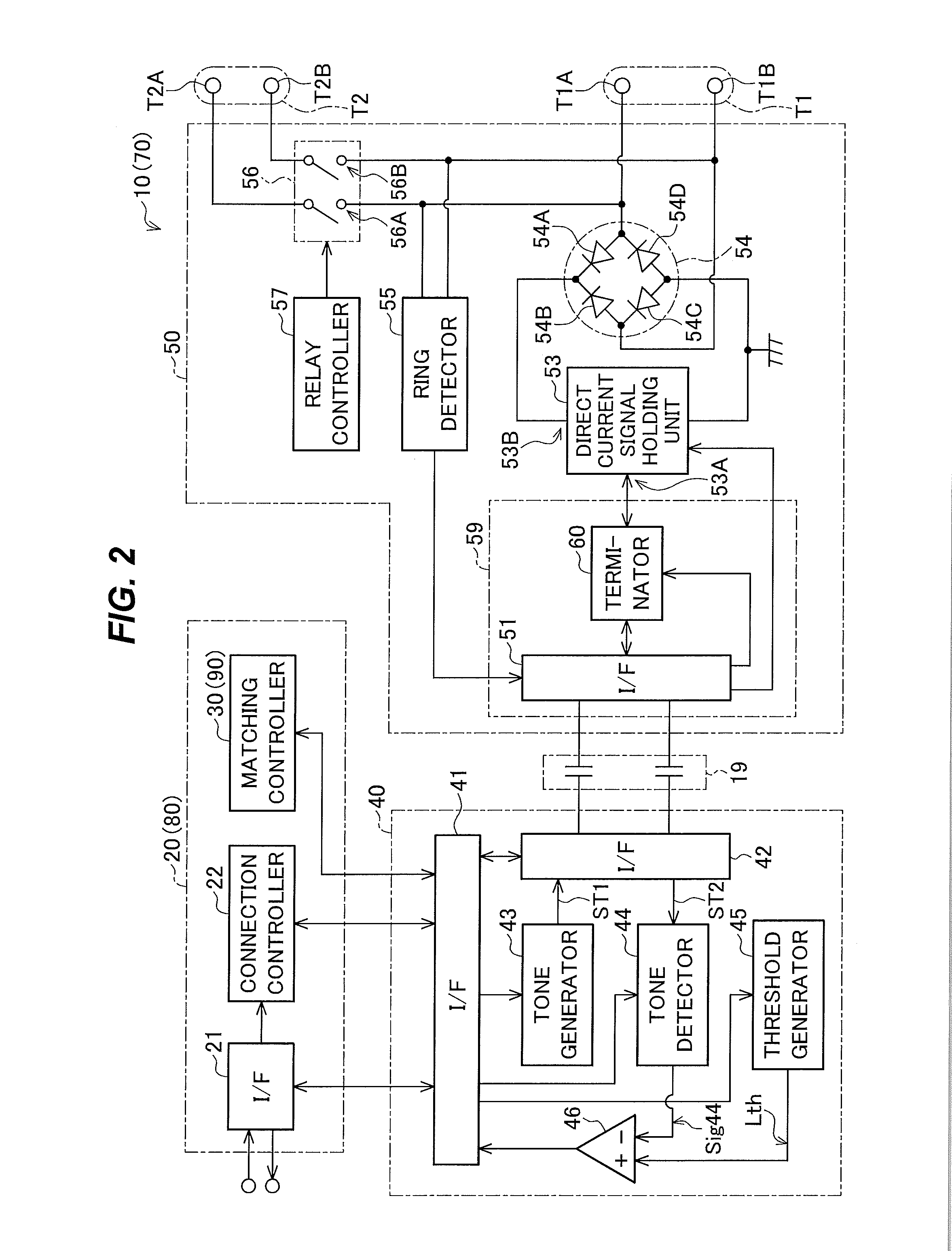
[0116]As illustrated in FIG. 1, the communication device 2 includes a line controller 70. As illustrated in FIG. 2, the line controller 70 includes a communication controller 80. The communication controller 80 includes a matching controller 90. The matching controller 90 determines the terminal impedance so that the difference (or impedance difference) between the terminal impedance of the communication device 2 and the line impedance of the telephone line 7 is reduced (or small), similarly to the matching controller 30 in the first embodiment. The...


PUM


Abstract

A communication device includes: a signal generator configured to generate a first signal and supply the first signal to a telephone line; a terminator having a variable terminal impedance as seen from the telephone line; a detector configured to detect a difference between the terminal impedance and a line impedance of the telephone line; and a controller configured to determine the terminal impedance so that the difference is reduced.

Description

BACKGROUND OF THE INVENTION[0001]1. Field of the Invention[0002]The present invention relates to a communication device for communication via a telephone line.[0003]2. Description of the Related Art[0004]Communication devices, such as telephones or facsimile machines, communicate with communication partners via telephone lines. There are multiple telephone line standards in the world, and the standards specify different line impedances of telephone lines. The terminal impedance of a communication device as seen from a telephone line is often set to a value corresponding to the line impedance of the telephone line (e.g., Japanese Patent Application Publication No. 2010-171636).[0005]However, the communication quality of a communication device may be degraded.SUMMARY OF THE INVENTION[0006]An aspect of the present invention is intended to improve communication quality.[0007]According to an aspect of the present invention, there is provided a communication device including: a signal gen...

Claims


Application Information

Patent Timeline
Patent Type & Authority Applications(United States)
IPC IPC(8): H04M1/76H04N1/00H04M19/02
CPCH04M1/76H04M19/02H04N2201/0093H04N1/00281H04N1/00206H04N1/32708H04N1/32715H04M3/28H04M11/066H04B3/493H04M3/305H04M7/0096
Inventor OGAWA, KIMIAKI
Owner OKI DATA CORP
Why Eureka
Try Eureka