Vehicle Charging Arrangement

Inactive Publication Date: 2017-03-23
FURRER FREY
View PDF11 Cites 14 Cited by
  • Summary
  • Abstract
  • Description
  • Claims
  • Application Information

AI Technical Summary

Benefits of technology

[0021]Insulating spacers may be provided on ends of the charge receiving conductors. Preferably, the insulating spacers are triangular. Each triangular spacer may have a first side parallel with and coincident with an end of its respective charge receiving conductor, a second side perpendicular to the first side, and a third side. The third side of each triangular spacer may be substantially parallel with the third side of an adjacent triangular spacer. In other words, adjacent triangular spacers substantially tessellate to form a two-part rectangular spacer between two adjacent charge receiving conductors. This arrangement is effective to prevent large debris from falling between and underneath the conductors. In that respect, the triangular spacers at either end of any given charge receiving conductor may have third sides substantially facing away from each other, towards opposing lateral sides of the row of charge receiving conductors.
[0022]A further advantage of the triangular spacers is that they prevent the charging conductors from dropping between the charge receiving members and getting caught, which could lead to significant and expensive damage.
[0023]The charge receiving connector may be installed on the roof of the veh

Problems solved by technology

Because the buses need charging relatively frequently, multiple charging stations may be required in a city or other operating area, and cost is therefore a particularly important factor.
The disclosed charging arrangement provides for a very good side-to-side and front-to-back docking tolerance with the charging station, but the equipment which must

Method used


Image

  • Vehicle Charging Arrangement
  • Vehicle Charging Arrangement
  • Vehicle Charging Arrangement

Examples


Example

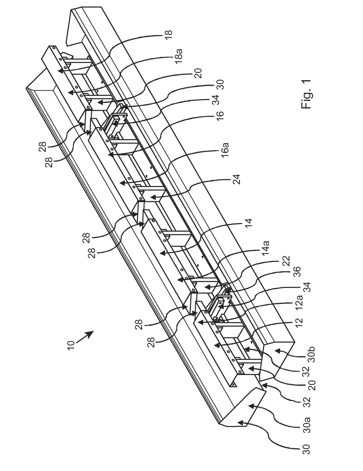
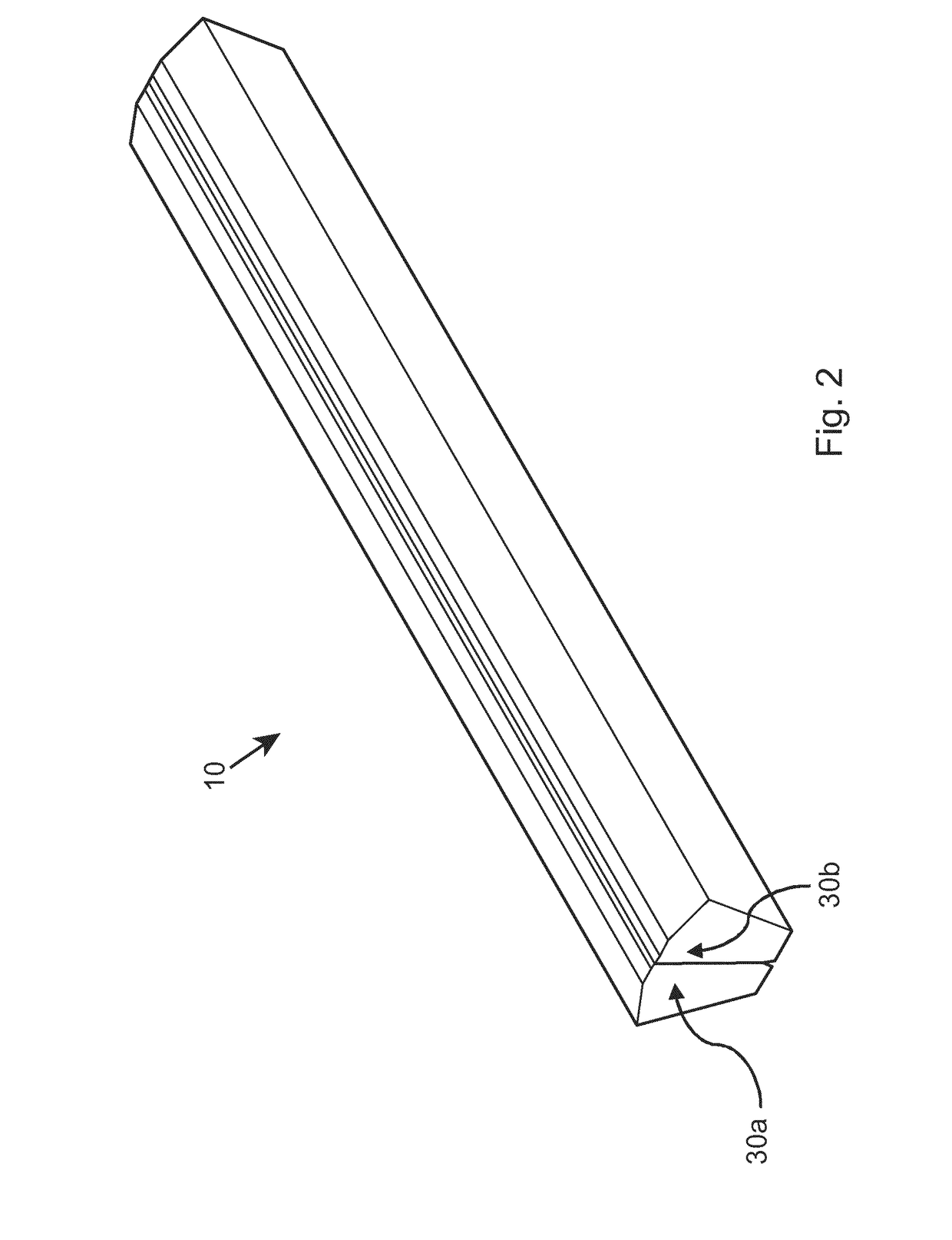
[0044]Referring firstly to FIG. 1, a charge receiving connector for a vehicle is indicated generally at 10. The charge receiving connector includes four charge receiving conductors 12, 14, 16, 18. The charge receiving connectors are substantially in the form of cuboids and are elongate, each having a longitudinal axis. The longitudinal axes of the elongate charge receiving conductors are disposed along the same line.

[0045]Each charge receiving conductor has a substantially planar contact face 12a, 14a, 16a, 18a. The contact faces are each substantially rectangular. On a side of each charge receiving conductor which opposes the contact face 12a, 14a, 16a, 18a, each conductor is fixed onto pivoting mounts 20, 22, 24, 26. Each pivoting mount comprises a pair of upright stands for securing to a vehicle, and pair of clamp sections for securing to the conductor. The clamp sections are secured to the conductor on the side opposing the contact face, each clamp section being disposed near an...


PUM


Abstract

A charging arrangement for a vehicle includes: a charge receiving connector secured to the roof of a vehicle at a fixed height from the roof of the vehicle, the charge receiving connector including at least three elongate charge receiving conductors longitudinal axes of the charge receiving conductors being disposed substantially along the same line; and a charging gantry including at least three charging conductors, the charging conductors being vertically movable between a raised position in which the charging conductors are clear of the vehicle when the vehicle is under the charging gantry, and a lowered position in which the charging conductors make contact with the charge receiving conductors on the roof of the vehicle.

Description

[0001]The present invention relates to a vehicle charging arrangement, and in particular to a vehicle charging arrangement suitable for charging electric buses and trucks.BACKGROUND TO THE INVENTION[0002]Electric vehicles are becoming increasingly practical, and electric buses in particular are beginning to be used on public service routes in cities throughout the world. Compared with traditional diesel-powered buses, electric buses have advantages in terms of reduced air pollution and quieter operation.[0003]Electric buses generally fall into two types. “Big battery” buses have large-capacity batteries, which are charged for a number of hours (for example, overnight) to provide enough range for a reasonably long journey. “Fast-charging” buses, on the other hand, have lower-capacity batteries which are designed to be charged very rapidly, to provide enough range for a shorter journey. The smaller batteries mean reduced overall weight of the vehicle and therefore more efficient opera...

Claims


Application Information

Patent Timeline
IPC IPC(8): B60L11/18B60L5/36B60L5/18B60L50/30
CPCB60L11/1827B60L5/18B60L2200/18B60L11/185B60L11/1816B60L5/36B60L1/003B60L3/0061B60L5/42B60M1/36B60L53/16B60L53/30B60L53/32B60L58/12B60L53/14B60L53/11B60L53/35Y02T10/70Y02T10/7072Y02T90/12Y02T90/14B60L50/30
Inventor BEDELL, ROGERSPANNAUS, THOMAS
Owner FURRER FREY
Why Eureka
Try Eureka