Sensing circuit, hybrid drive circuit, and sensor assembly

a sensor circuit and hybrid drive technology, applied in the field of sensing circuits, can solve the problems that the vehicle battery management system cannot work effectively, and achieve the effect of improving reliability and reducing product output dri

Active Publication Date: 2017-03-23
TYCO ELECTRONICS (SHANGHAI) CO LTD
View PDF52 Cites 4 Cited by
  • Summary
  • Abstract
  • Description
  • Claims
  • Application Information

AI Technical Summary

Benefits of technology

[0036]The present invention provides a sensing circuit and a sensor assembly, comprising a sensor and a hybrid drive circuit. The hybrid drive circuit mainly comprises a driving apparatus (a drive circuit). The driving apparatus comprises a current drive circuit and a voltage drive circuit. The current drive circuit drives the sensor in a current drive mode, and the voltage drive circuit drives the sensor in a voltage drive mode. The hybrid drive circuit further comprises a switch apparatus connected to the driving apparatus. The switch apparatus controls the driving apparatus, to enable the driving apparatus to switch between the current drive mode and the voltage drive mode. According to the present invention, a temperature testing circuit with a negative temperature coefficient thermistor being the main component is further used to sense ambient temperature of the sensor, and the input voltage of the switch apparatus is changed by means of that the resistance of the thermistor changes as the temperature changes, so as to control the on and off state of the switch apparatus, to switch the drive mode of the Hall sensor. Therefore, the sensor is driven in different modes at different temperatures, so that the zero drift of the output of the product is reduced, and reliability of a vehicle battery management system is improved.

Problems solved by technology

According to design of an existing sensor (for example, a Hall sensor), a zero-drift phenomenon occurs at extreme high and low temperatures (especially at subzero temperatures): e.g., when a magnetic field is zero, an abnormal sensing signal is sent by the sensor, which makes the vehicle battery management system cannot work effectively.

Method used


Image

  • Sensing circuit, hybrid drive circuit, and sensor assembly
  • Sensing circuit, hybrid drive circuit, and sensor assembly
  • Sensing circuit, hybrid drive circuit, and sensor assembly

Examples


Embodiment Construction

[0043]Various embodiments of the present invention are described below with reference to the accompanying drawings that constitute a part of the specification. It should be understood that, although directional terms used in the present invention, such as “front”, “rear”, “upper”, “lower”, “left”, and “right”, refer to exemplary structural parts and elements in the present invention, these terms used herein are only for ease of description, and are determined based on exemplary directions shown in the accompanying drawings. The embodiments disclosed by the present invention may be disposed according to different directions, so that these directional terms are for illustration only, but shall not be construed as limiting the present invention. In possible cases, the same or similar reference signs used in the present invention refer to the same components.

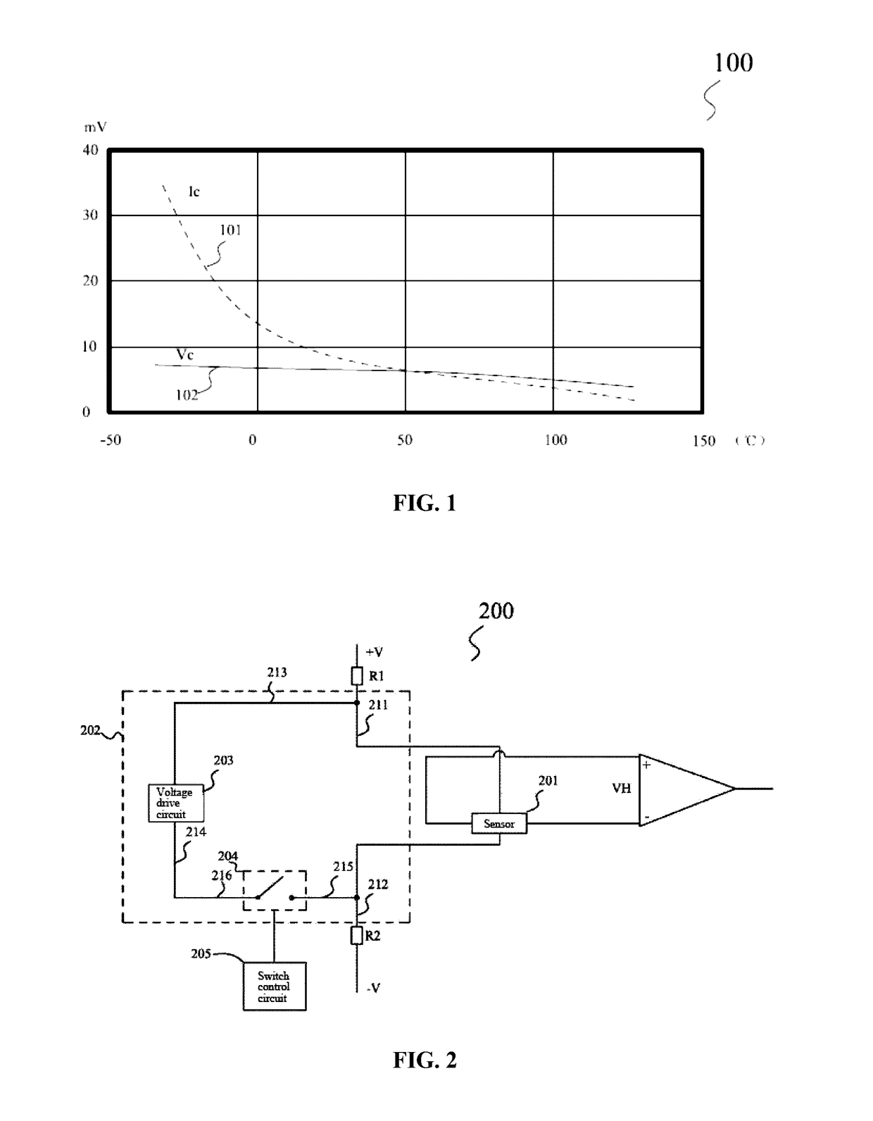
[0044]FIG. 2 is a schematic view of the basic structure of a sensing circuit 200 according to the present invention. As shown in F...


PUM


Abstract

The invention provides a sensing circuit having a driving apparatus, that is, a current drive circuit and a voltage drive circuit. The current drive circuit drives a sensor in a current drive mode, and the voltage drive circuit drives the sensor in a voltage drive mode. The sensing circuit further has a switch apparatus connected to the driving apparatus for controlling the driving apparatus, to enable the driving apparatus to switch between the current drive mode and the voltage drive mode. A temperature testing circuit with a negative temperature coefficient thermistor is further used to sense ambient temperature of the sensor, and the input voltage of the switch apparatus is changed by means of that the resistance of the thermistor changes as the temperature changes, so as to control on and off of the switch apparatus, to switch the drive mode of the sensor.

Description

CLAIM OF PRIORITY[0001]The present application claims priority from Chinese patent application CN 201520726421.2, filed Sep. 18, 2015; the subject matter of which is incorporated herein by reference.TECHNICAL FIELD[0002]The present invention relates to a vehicle battery management system, and particularly to a sensing circuit for monitoring battery charging and discharging states and a related assembly.BACKGROUND[0003]Sensors have been used to dynamically monitor the charging / discharging current and working state of a vehicle battery, and feed back an acquired signal to a battery management system. The battery management system manages and controls the battery appropriately and effectively in conjunction with other acquired performance parameter(s), so as to ensure desirable battery performance and normal operation of electrical equipments.[0004]According to design of an existing sensor (for example, a Hall sensor), a zero-drift phenomenon occurs at extreme high and low temperatures...

Claims


Application Information

Patent Timeline
Patent Type & Authority Applications(United States)
IPC IPC(8): B60L11/18H02J7/00
CPCB60L11/1861B60L2260/26H02J7/0068H02J7/007G01R33/07G01R15/202G01R19/32G01R31/382Y02T10/70G01R31/3842G01R1/206G01R19/16542G01R19/16576G01R31/36
Inventor SUN, YEMAO, XINHUIZHOU, JIACHENGZHOU, JIANWU
Owner TYCO ELECTRONICS (SHANGHAI) CO LTD
Why Eureka
Try Eureka