Vehicle alternator

a technology of vehicle alternator and rotor, which is applied in the direction of magnetic circuit rotating parts, magnetic circuit shape/form/construction, windings, etc., can solve the problems of increasing the temperature of various components forming the vehicle alternator, increasing the thermal energy of the component, and increasing the size of the mounting space etc., to enhance the reliability of the vehicle alternator, good bonding state, and thermal stress applied to the bonding material

Inactive Publication Date: 2007-05-17
DENSO CORP
View PDF20 Cites 1 Cited by
  • Summary
  • Abstract
  • Description
  • Claims
  • Application Information

AI Technical Summary

Benefits of technology

[0011] The thermal stress applied to the bonding material through which the cooling fin part is bonded to the heat sink can be reduced by making the cooling fin part and the heat sink of the regulator with one or more materials which is a same thermal expansion coefficient. This feature maintains the good bonding state between the heat sink and the cooling fin part over a long time and thereby enhances the reliability of the vehicle alternator according to the present invention.
[0012] According to another aspect of the present invention, there is provided a vehicle alternator in which both of the cooling fin part and the heat sink are made of copper or copper alloy. By making the cooling fin part and the heat sink of the regulator with copper or copper alloy of a superior thermal expansion coefficient, it is possible to achieve both the reduction of thermal stress and the increase of the cooling capability, and thereby to enhance the reliability of the vehicle alternator. For example, when compared with the vehicle alternator in which both the cooling fin part and the heat sink are made of aluminum, it is possible to greatly increase the cooling capability of the vehicle alternator according to the present invention.
[0013] Still further, according to another aspect of the present invention, there is provided the vehicle alternator in which an outer diameter of the stator is not more than 152 mm, and a rated output voltage of the vehicle alternator is not less than 2.4 kW. Even if the vehicle alternator is a large sized vehicle alternator and has a large rated output, it is possible to certainly maintain the improved bonding condition between the regulator heat sink and the regulator cooling fin part, and thereby possible to have both the high reliability and the large output of the vehicle alternator.
[0014] Still further, according to another aspect of the present invention, there is provided the vehicle alternator in which an outer diameter of the stator is not more than 152 mm and a rated output voltage of the vehicle alternator is not less than 2.4 kW Even if the vehicle alternator is a large size and a large output, it is possible to maintain the connection state between the regulator heat sink and the regulator cooling fin part certainly and thereby possible to achieve both the high output capability and a high reliability of the vehicle alternator.

Problems solved by technology

Recently, the mounting space of a vehicle alternator has become more and more limited because of reduction in engine-mounting space in a vehicle caused by a tendency for a slant-nosed design of the front part of a vehicle for reducing running resistance of a vehicle such as air resistance and the need to enlarge a vehicle compartment space.
However, the temperature of various components forming the vehicle alternator is thereby increased and the thermal energy thereof deteriorates those components.
This introduces the difficulty to maintain the adhesion between the cooling fins and the heat sink over a long time and thereby decreases the reliability of the vehicle alternator.
The deterioration of the adhesion condition between them causes malfunction of the electric power generation of the vehicle alternator because the radiating capability of the regulator becomes worse.

Method used


Image

  • Vehicle alternator
  • Vehicle alternator
  • Vehicle alternator

Examples


embodiment

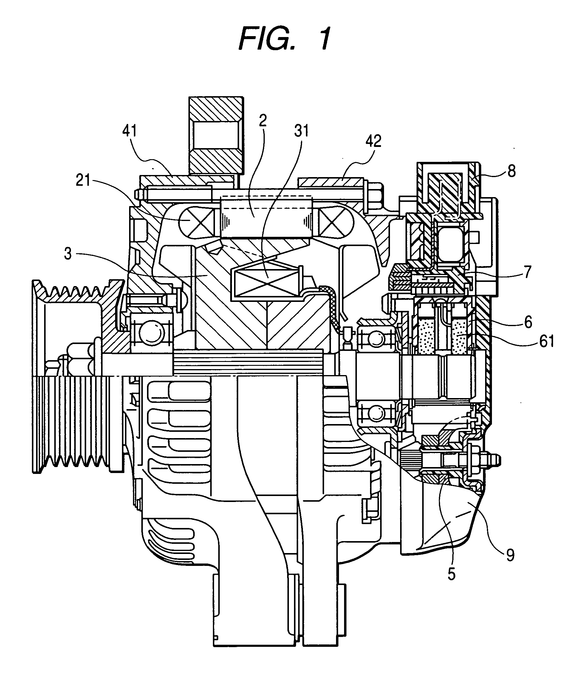
[0024] A description will be given of the vehicle alternator according to the embodiment of the present invention with reference to FIG. 1 to FIG. 7.

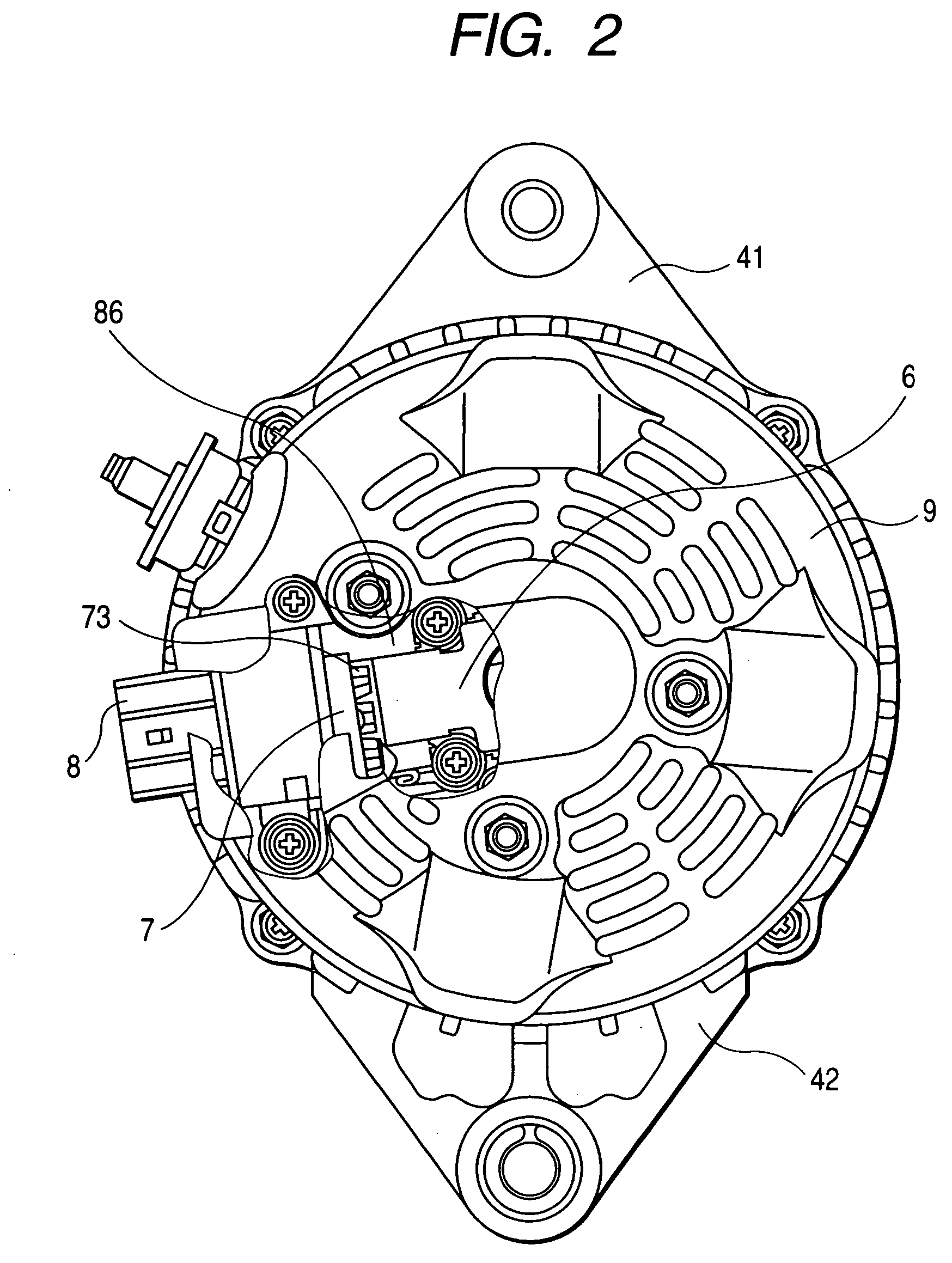
[0025] FIG.1 is a schematic view of an entire configuration of the vehicle alternator according to the embodiment of the present invention. FIG. 2 is a rear view of the vehicle alternator shown in FIG. 1.

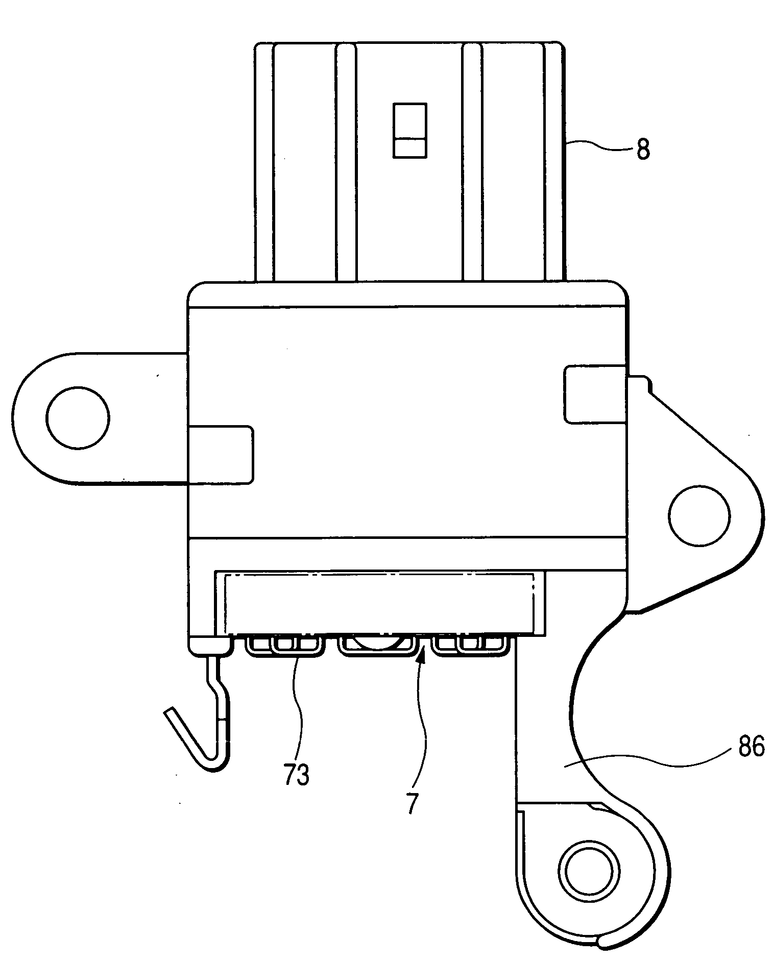
[0026] As shown in FIG. 1 and FIG. 2, the vehicle alternator 1 has a stator 2, a rotor 3, a front housing 41, a rear housing 42, a rectifier device 5, a brush device 6, a regulator case 7, a connector case 8, and a rear cover 9.

[0027] The stator 3 acts as an armature having a stator winding 21. The rectifier device 7 rectifies the three-phase output current from the stator winding 21 and provides a rectified direct current. The rotor 3 acts as a field magnet, which is composed of two parts that are placed on opposite faces to each other. The front housing 41 and the rear housing 42 support the stator 2 and the rotor 3. The rectifier ...


PUM


Abstract

A vehicle alternator for generating electric power has a stator, a rotor, a rectifier, a regulator case, and a cooling fin part. A stator winding is wound on the stator. The rotor is placed on opposite faces to the stator. The rectifier rectifies an alternating current output voltage excited in the stator winding. The regulator case accommodates a regulator substrate for adjusting the output voltage and a heat sink. On one surface of the heat sink the regulator substrate is mounted. The cooling fin part has plural cooling fins bonded to the other surface of the heat sink. The cooling fin part and the heat sink are made of a same material of a superior thermal expansion coefficient, such as copper or copper alloy.

Description

CROSS-REFERENCE TO RELATED APPLICATIONS [0001] This application is related to and claims priority from Japanese Patent Application No. 2005-328694 filed on Nov. 14, 2005, the contents of which are hereby incorporated by reference. BACKGROUND OF THE INVENTION [0002] 1. Field of the invention [0003] The present invention relates to a vehicle alternator equipped with a regulator of an improved adhesion condition between a heat sink and cooling fins, and the vehicle alternator is mounted on a vehicle such as a passenger car or a truck. [0004] 2. Description of the Related Art [0005] Recently, the mounting space of a vehicle alternator has become more and more limited because of reduction in engine-mounting space in a vehicle caused by a tendency for a slant-nosed design of the front part of a vehicle for reducing running resistance of a vehicle such as air resistance and the need to enlarge a vehicle compartment space. [0006] Further, in order to increase the fuel consumption of a vehic...

Claims


Application Information

Patent Timeline
Patent Type & Authority Applications(United States)
IPC IPC(8): H02K3/24H02K11/04
CPCH02K19/365H02K9/02H02K19/24H02K19/36
Inventor HAMADA, HIROSHIHAYASHI, YOSHINORIMASHINO, MIKIOKONDOU, YOSHITAKA
Owner DENSO CORP
Why Eureka
Try Eureka