

Heat dissipation structure and vehicular inverter
Inactive Publication Date: 2010-03-04
TOYOTA JIDOSHA KK
View PDF37 Cites 1 Cited by
- Summary
- Abstract
- Description
- Claims
- Application Information
AI Technical Summary
Benefits of technology
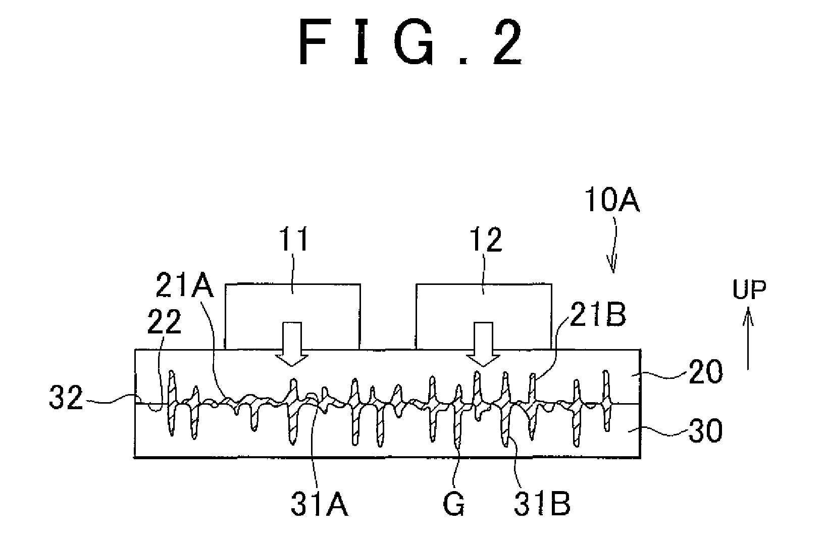
[0018]In the heat dissipation structure according to the second aspect of the invention, the thermally conductive grease on the first contact region can be restrained from flowing by providing the plurality of the pores in the first contact region on which the thermally conductive grease is disposed. Furthermore, in this heat dissipation structure, the second contact region is so provided as to surround the first contact region. Therefore, as is the case with the foregoing first embodiment of the invention, the oil component of the thermally conductive grease disposed on the first contact region seldom flows to the second contact region through the capillary phenomenon. As a result, in this heat dissipation structure, an air layer is unlikely to be formed on the first contact region through the flow of the thermally conductive grease, and the oil component of the thermally conductive grease is unlikely to flow out. Thus, the performance of heat dissipation of this heat dissipation structure does not deteriorate. In this heat dissipation structure, heat of the heating element laid on the substrate is radiated from the heat dissipation member via the thermally conductive grease.
[0019]Furth
Problems solved by technology
When the heat dissipation structure described in Japanese Patent Application Publication No. 2006-49501 (JP-A-2006-49501) is adopted, although the thermally conductive grease itself is unlikely to flow, the irregularity of the surfaces may separate only an oil component of the thermally conductive
Method used
View moreImage
Smart ImageViewing Examples

Examples
 PUM
| Property | Measurement | Unit |
|---|---|---|
| Width | aaaaa | aaaaa |
| Surface roughness | aaaaa | aaaaa |
| Surface roughness | aaaaa | aaaaa |
Abstract
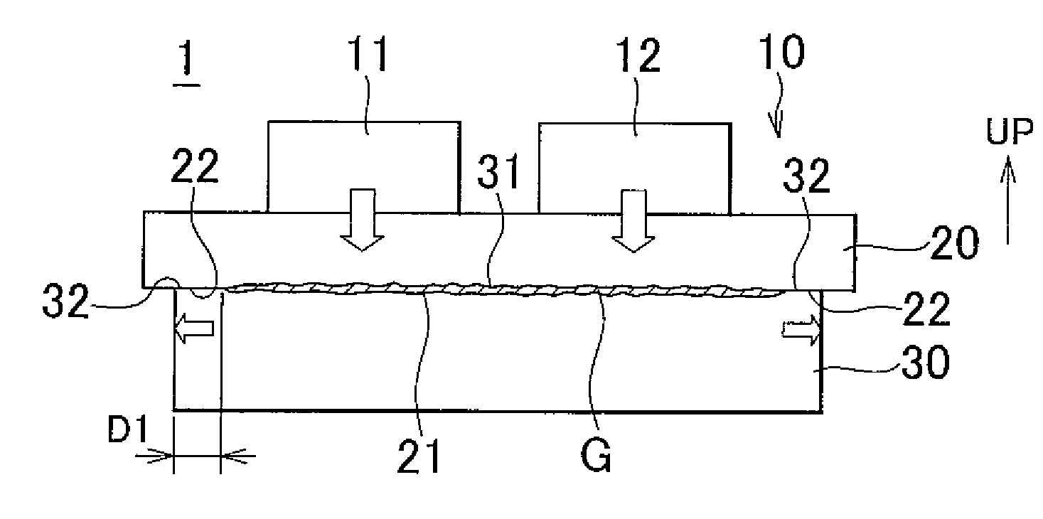
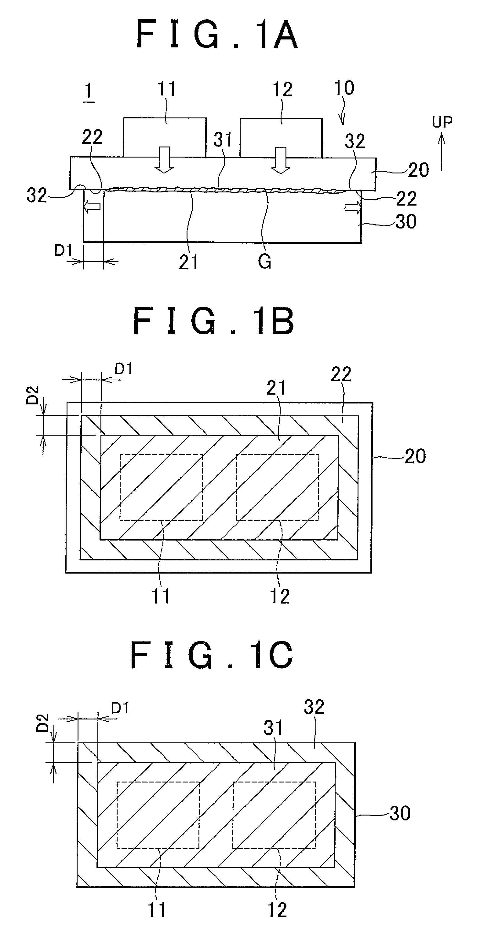
A heat dissipation structure is equipped with a heating element; a substrate, on which the heating element is provided; and a heat dissipation member that is in contact with the substrate via thermally conductive grease. The substrate and the heat dissipation member have contact surfaces that are in contact with each other, and at least one of the contact surfaces has a first contact region on which the thermally conductive grease is disposed, and a second contact region that surrounds the first contact region. A surface roughness of the second contact region is lower than a surface roughness of the first contact region.
Description
INCORPORATION BY REFERENCE[0001]The disclosure of Japanese Patent Application No. 2008-217071 filed on Aug. 26, 2008 including the specification, drawings and abstract is incorporated herein by reference in its entirety.BACKGROUND OF THE INVENTION[0002]1. Field of the Invention[0003]The invention relates to a heat dissipation structure for dissipating heat from a heating element, and more particularly, to a heat dissipation structure suited to dissipate heat by taking advantage of grease.[0004]2. Description of the Related Art[0005]A vehicular inverter or the like mounted with electronic components adopts a heat dissipation structure. For example, a power control unit for the vehicular inverter is composed of an inverter portion and a boost converter portion. As shown in FIG. 5, a boost converter has disposed in a case (substrate) 70 thereof a boost intelligent power module (boost IPM) 11 and a reactor 12. The boost IPM 11 and the reactor 12 are heating elements that generate heat w...
Claims
Login to View More Application Information
Patent Timeline
 IPC IPC(8): H05K7/20F28F7/00F28F21/00
CPCF28F13/00H05K3/0061H05K7/209H05K3/386H05K2201/0116H05K3/382
InventorONO, MARI
OwnerTOYOTA JIDOSHA KK