Optical wave guide having multiple independent optical path and optical gas sensor using that

a technology of optical gas sensor and optical path, which is applied in the direction of optical radiation measurement, instruments, spectrophotometry/monochromators, etc., can solve the problems of ineffective use of light, inability to adequately irradiate to an optical sensor, and relatively short optical path, so as to reduce the amount of light loss and minimize light reflection

Active Publication Date: 2017-03-23
KOREA NAT UNIV OF TRANSPORTATION IND ACADEMIC COOP FOUND
View PDF15 Cites 1 Cited by
  • Summary
  • Abstract
  • Description
  • Claims
  • Application Information

AI Technical Summary

Benefits of technology

[0029]Another objective of the present invention is to provide an optical wave guide having multiple independent optical path and optical gas sensor using that that reduces loss of amount of light and at the same time allows light to condense properly to an optical sensor part by realizing a structure with a long optical path and a structure minimizing reflection of light.

Problems solved by technology

This structure is a structure using only less than half of light flux of an irradiating light, in the case of light irradiating and reflecting in lower flat surfaces, there are disadvantages of difficulty of adequately irradiating to an optical sensor (12) when passing though a filter attached to an optical sensor (12) due to refraction.
But, the optical wave guide (110) of Korean Patent No. 10-1088360 structurally inherits disadvantages of condensing maximum of only ¼ of light from two light detecting windows.
But the structure using only two parabolic mirrors (151, 152), as proposed by J. S. Park and S. H. Yi in Sensors and Materials (thesis in year 2011), is a structure having disadvantages of not being able to effectively use light because condensing pattern shows a shape other than a round shape.
But, there are disadvantages of optical path being relatively short, and increased manufacturing costs due to installation of additional lens.
The structure proposed in Korean Patent Laid-open Publication 2011-59006, as illustrated in FIG. 5, has advantages of being able to improve light intensity by adopting a lens in front of an infrared sensor (174), but has disadvantages of increase in cost due to use of additional components and amount light arriving at an optical sensor part becoming relatively small by adopting a reflector (172) to increase optical path.
But has structural disadvantages of having lower optical sensor part (230) output compared to that of a structure with a lens because there is no special structure to condense incident infrared rays in the front-end of a photo sensor part (230).
But, it may show disadvantages of being difficult to use for gas measurements for long wavelength ranges (>6 μm) as pattern of light arriving at an infrared sensor (350) incidents in parallel.

Method used


Image

  • Optical wave guide having multiple independent optical path and optical gas sensor using that
  • Optical wave guide having multiple independent optical path and optical gas sensor using that
  • Optical wave guide having multiple independent optical path and optical gas sensor using that

Examples


example 1

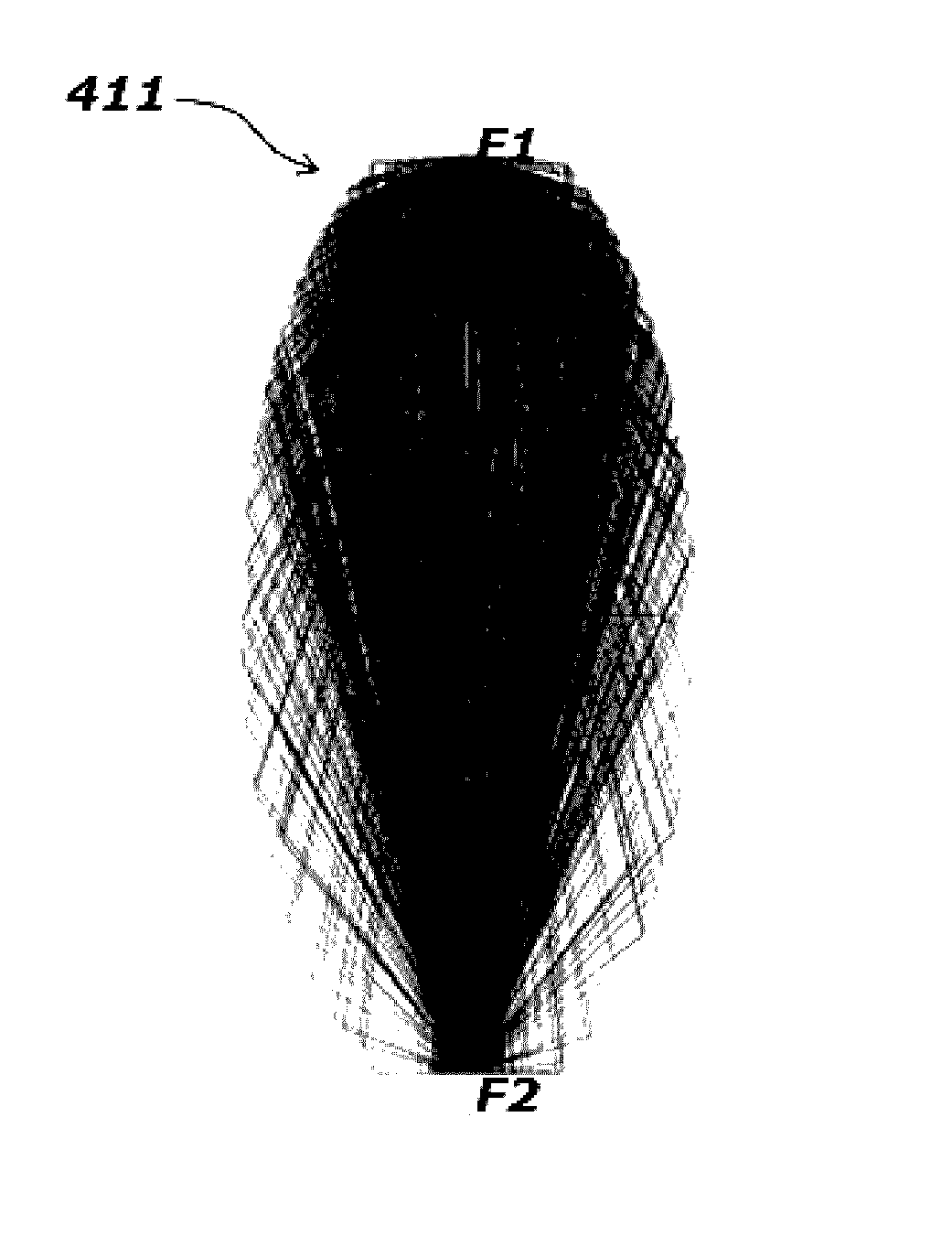
[0082]an optical wave guide is realized by two 3 dimensional elliptical mirrors, a light source is installed at a second focal point (F2) of one of the elliptical mirrors, and an optical sensor part is installed at a second focal point (F2) of another elliptical mirror.

[0083]FIG. 11A is drawing illustrating an optical wave guide having multiple independent optical path in accordance with example 1 of the present invention, and FIG. 11B illustrates results of simulation of shape of light flux arriving at an optical sensor part, and FIG. 12 illustrates energy of incident light per unit area according to angles between major axis of two 3 dimensional elliptical mirrors, and FIG. 13A, FIG. 13B and FIG. 13C illustrate results of simulation of shape of light flux arriving at an optical sensor part according to angles between major axis of two 3 dimensional elliptical mirrors, and FIG. 14 illustrates relationship between radius of condensation of incident light arriving at an optical senso...

example 2

[0092]an optical wave guide is realized by two 3 dimensional elliptical mirrors, an optical sensor part is installed at a first focal point (F1), which is a common focal point, and light sources are installed at each second focal points (F2) of two 3 dimensional elliptical mirrors

[0093]As in example 2, when an optical wave guide is configured, it is difficult to condense light irradiating from two light sources within tens˜hundreds μm radius (in other words, Field of View) from the center of an optical sensor part. The reason is that light irradiating from two light sources causes interference.

example 3

[0094]an optical wave guide is realized by two 3 dimensional elliptical mirrors, a light source is installed at a first focal point (F1), which is a common focal point, and optical sensor parts are installed at each second focal points (F2) of two 3 dimensional elliptical mirrors

[0095]FIG. 15 illustrates optical paths when an optical wave guide having multiple independent optical path in accordance with the present invention has two elliptical mirrors, FIG. 16A, FIG. 16B and FIG. 17 illustrate results of simulation of energy of light per unit area arriving at a left side and right side according to change in angles between major axis of 3 dimensional elliptical mirrors according to structure illustrated in FIG. 15, FIG. 18A, FIG. 18B, FIG. 18C and FIG. 18D illustrate a shape of an optical flux of an incident light arriving at an optical sensor part according to change in angles between major axis according to structure illustrated in FIG. 15.

[0096]First, referring to FIG. 15, it ill...


PUM

PropertyMeasurementUnit
angleaaaaaaaaaa
angleaaaaaaaaaa
wavelength rangesaaaaaaaaaa

Abstract

The present disclosure relates to an optical gas sensor including at least: an optical wave guide including a first elliptical mirror formed along at least part of a first 3-dimensional ellipsoid and having a first focal point and a second focal point, a second elliptical mirror formed along at least part of a second 3-dimensional ellipsoid and having the first focal point and a third focal point, and a third elliptical mirror formed along at least part of a third 3-dimensional ellipsoid and having the first focal point and a fourth focal point; one or more optical sensors installed at at least one of the first, second, third, and fourth focal points; and one or more light sources installed at at least one of the first, second, third, and fourth focal points where the one or more optical sensors are not installed.

Description

CROSS REFERENCE TO RELATED APPLICATION[0001]The present application is a divisional application of U.S. patent application Ser. No. 14 / 264,575 filed on Apr. 29, 2014, which claims the benefit of priority from Korean Patent Application No. 10-2014-0012013, filed on Feb. 3, 2014, in Korean Intellectual Property Office (KIPO). The disclosures of the above-listed applications are hereby incorporated by reference herein in their entirety.DESCRIPTION[0002]Field of Invention[0003]The present invention relates to optical wave guide having multiple independent optical path and optical gas sensor using that, and more particularly providing an optical wave guide having multiple independent optical path and Optical Gas Sensor using that that may condense light irradiating from a light source without a separate condenser within a range of tens˜hundreds μm from the center of an optical sensor part, and reducing loss of amount of light by realizing a structure with a long optical path and also a s...

Claims


Application Information

Patent Timeline
Patent Type & Authority Applications(United States)
IPC IPC(8): G01J1/42G01J1/04G01N21/3504
CPCG01J1/4228G01N2201/08G01J1/0422G01N21/3504G01J3/021G01J3/42G01J3/0216G02B19/0085G02B19/009G01N21/031G01N21/05G02B19/0023G02B6/10G02B27/106G02B2207/117
Inventor LEE, SEUNG HWANJANG, SUNG HOJUNG, SANG HO
Owner KOREA NAT UNIV OF TRANSPORTATION IND ACADEMIC COOP FOUND
Why Eureka
Try Eureka