Semi-flexible proof-mass

a micro-mechanical device and mass technology, applied in the direction of flexible micro-structural devices, structural/machine measurement, instruments, etc., can solve the problems of stiction, cracking or fracture of mems structures, and breaking of structures, so as to prevent sticking, prevent cracking or fracture effectively, and the manufacturing process is relatively simple.

Active Publication Date: 2017-03-23
MURATA MFG CO LTD
View PDF10 Cites 34 Cited by
  • Summary
  • Abstract
  • Description
  • Claims
  • Application Information

AI Technical Summary

Benefits of technology

[0015]Coupling the semi-flexible proof-mass towards suspension structures such as anchors with main springs attached to the secondary part(s), is especially beneficial in case of sticking and for preventing sticking. Term sticking indicates a known problem of microelectromechanical structures, where two surfaces of the structure coming into contact with each other may stick together. By suspending the semi-flexible proof-mass from the secondary part(s), when both the primary and secondary parts have come to a contact with a stopper structure, all restoring forces caused by the main spring(s) and the stiff spring(s) act towards dislodging the secondary part(s) from the contact. Thus, the configuration effectively prevents sticking. The restoring force caused by the main spring(s) sums with the restoring force caused by the stiff spring(s), and the total restoring force acts to dislodge the secondary part. Furthermore the momentum of the moving secondary part helps to dislodge the primary part and return the device into its normal operation position. The semi-flexible proof-mass is preferably formed as a substantially planar structure, situated in a plane. Structural parts of the semi-flexible proof-mass are preferably situated in a common plane, which may comprise the plane of the device. For example, a semi-flexible proof-mass capable to deflect along at least one axis of movement within the plane of the device may comprise a structure etched from an essentially planar, homogenous silicon material layer having a non-zero thickness. Thus, the manufacturing process is relatively simple, which increases manufacturing process gain and facilitates uniform performance of the multiple devices created on the same silicon wafer. Thickness of the material layer of the semi-flexible proof-mass may vary without departing from the scope. Selected areas of the proof-mass structure may be recessed below either of the horizontal (xy-plane direction) surfaces of the silicon material layer. The material of the semi-flexible proof-mass is preferably removed in areas between the primary and secondary parts, except for the coupling stiff springs, in order to allow the semi-flexible proof-mass to deform in set circumstances.
[0016]The present invention has the advantage that a solution based on deforming of a semi-flexible proof-mass is an effective and reliable way to prevent both structure breakage and stiction. A semi-flexible multi-part proof-mass structure may even be combined with various rigid or flexible stopper or bumper solutions known by a person skilled in the art.

Problems solved by technology

One failure mechanism known for MEMS devices is stiction, which means adhesion of structural components to one another or to a substrate, material from which the structure is made of.
Another known failure mechanism is breakage, such as cracking or fracture of MEMS structures due to impact.
A single, hard impact may cause cracking or fracture of a MEMS structure, or several repeated impacts may cause fatigue of MEMS structure which eventually leads to breaking of the structure.
When the device is subject to mechanical shock, the secondary structure causes the secondary mass to impact the movable element so that it's likely dislodged if stuck after the impact.
A problem relating to the prior art US2012 / 0280591 is that although the secondary structure enables relief from sticking problem, the movable mass may be damaged due to the impact caused by a shock.
Term sticking indicates a known problem of microelectromechanical structures, where two surfaces of the structure coming into contact with each other may stick together.

Method used


Image

  • Semi-flexible proof-mass
  • Semi-flexible proof-mass
  • Semi-flexible proof-mass

Examples


Embodiment Construction

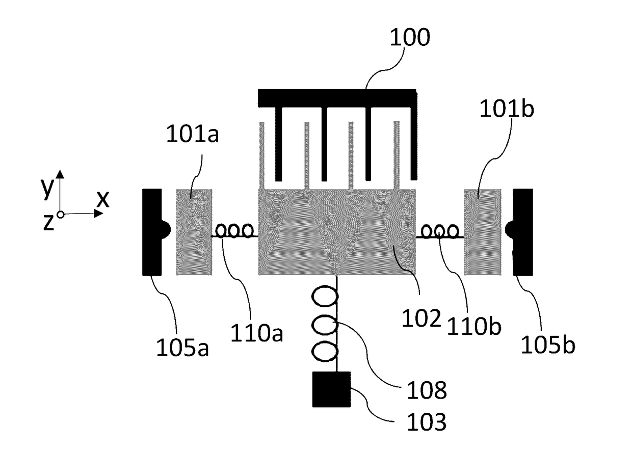
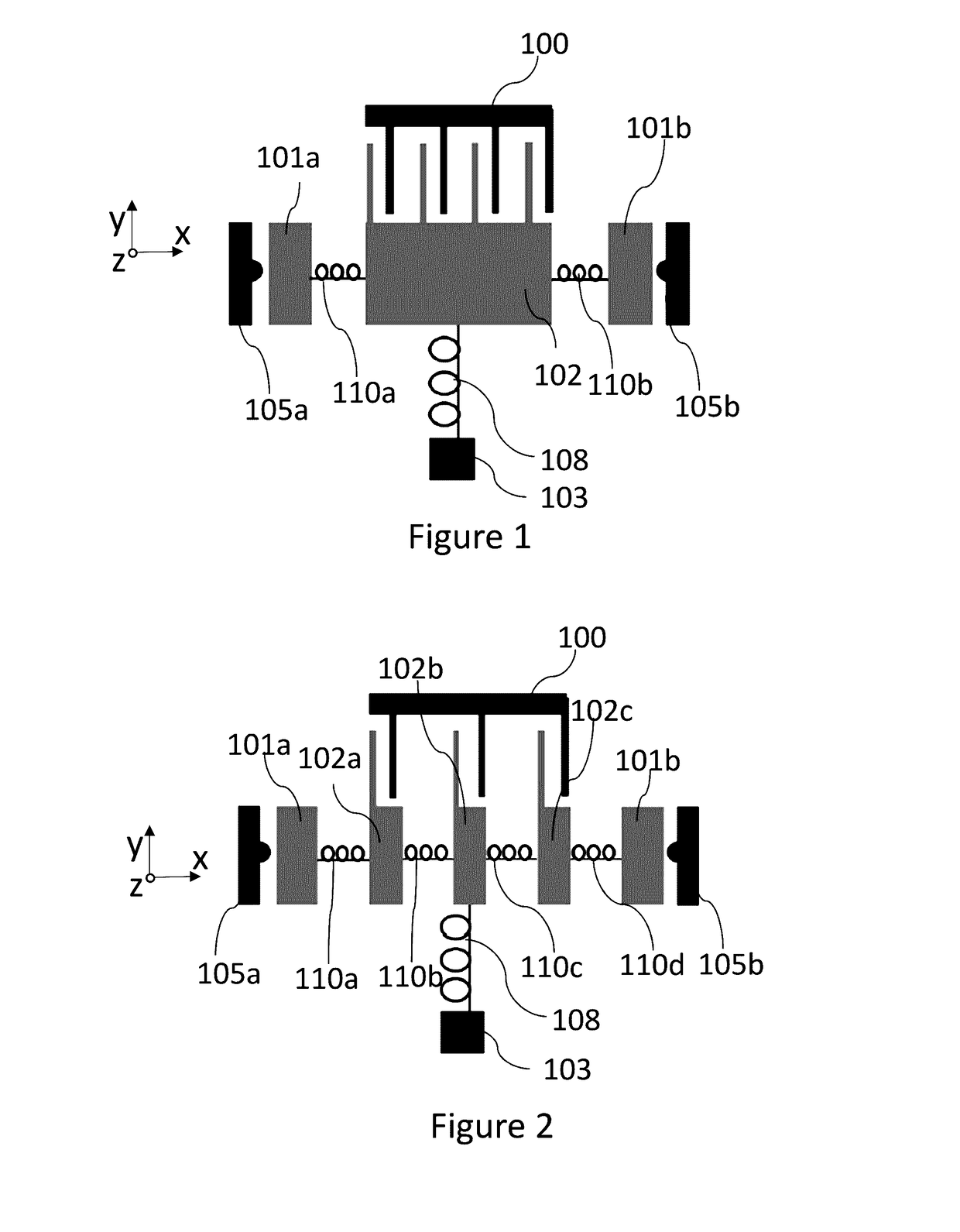
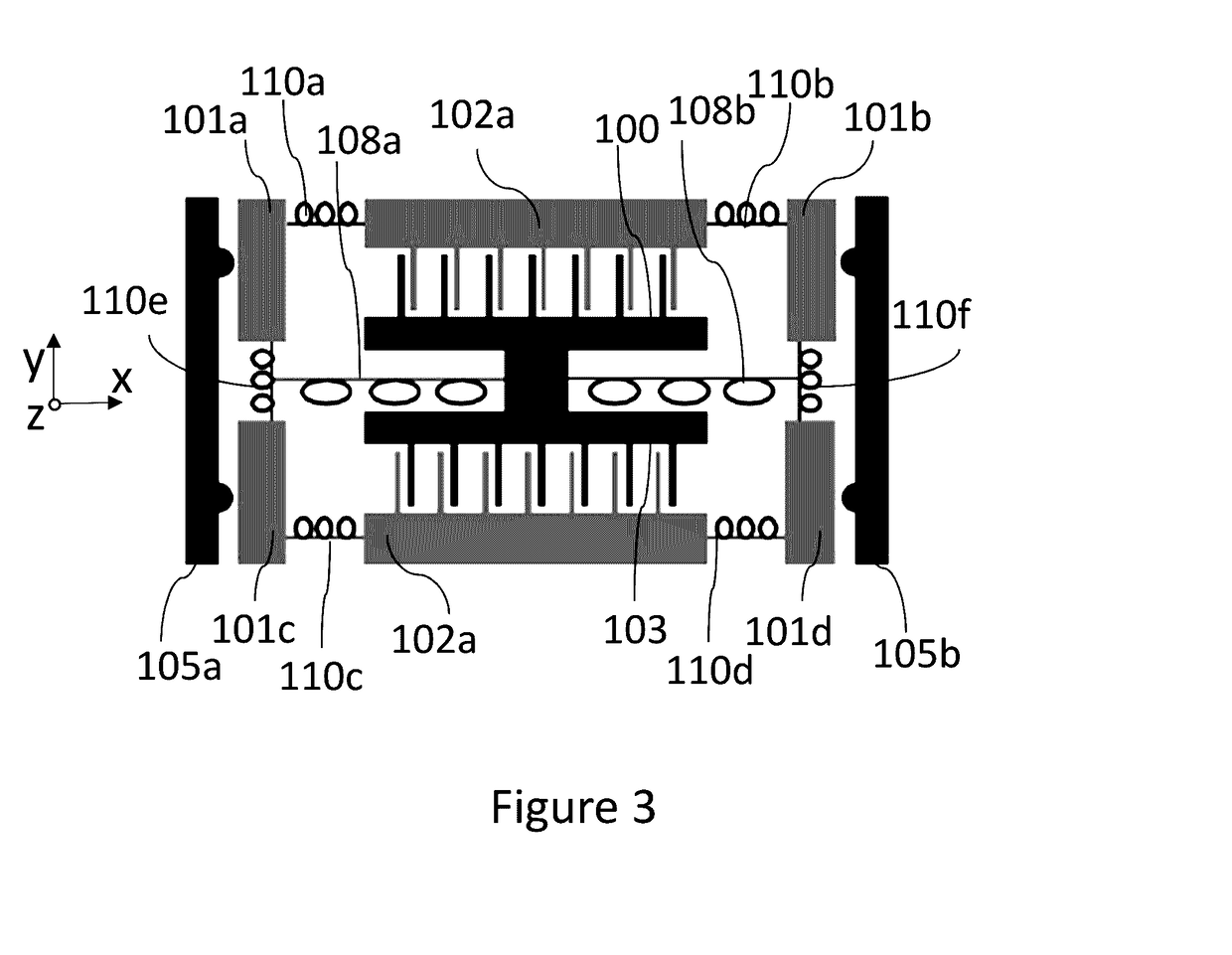
[0044]A MEMS device may comprise a substrate layer and a functional layer suspended above the substrate layer. Fixed or stationary structures of the functional layer are suspended above the substrate layer, and movable structures of the functional layer are movably suspended above the substrate layer. Example of movable structures of a MEMS device are movable masses such as a proof-mass, springs and moving fingers electrode combs.

[0045]A spring in a MEMS device may be considered as a suspension structure that constrains motion of the suspended structure in defined dimensions. Springs may have varying form depending on the functionality they are intended to. A rectilinear beam may act as a spring, and dimensions of the beam define the characteristics of the spring. A MEMS spring may comprise two or more rectilinear sections, forming a fold, crab leg, a U-shape or a serpentine, for example. FIGS. 1 to 3 illustrate functionality of springs in functional manner only, i.e. the physical f...


PUM


Abstract

A microelectromechanical device includes a semi-flexible proof-mass comprising a primary part, a secondary part and a stiff spring suspending the primary part and the secondary part. The spring causes the parts to move as a single entity when the device is in its normal range. A first stopper structure stops the primary part. The proof-mass is configured to deform through deflection of the spring, when the device is subjected to a shock having a force that is beyond the normal operation range. While the shock causes motion of the proof-mass in one direction along an axis of movement, the spring is configured to cause a restoring force causing the secondary part of the proof-mass to be driven into a restoring motion in a direction opposite to motion along an axis caused by the shock. Momentum of the secondary part causes the primary part to dislodge from the first stopper structure.

Description

BACKGROUND[0001]Field[0002]The present invention relates to a micromechanical device.[0003]Description of the Related Art[0004]Micro-Electro-Mechanical Systems, or MEMS, can be defined as miniaturized mechanical and electro-mechanical systems where at least some elements have a mechanical functionality. Since MEMS devices are created with the same or similar tools used to create integrated circuits, micromachines and microelectronics can even be fabricated on the same piece of silicon. MEMS structures can be applied to quickly and accurately detect very small changes in physical properties.[0005]While being very small in size, MEMS structures have different and unique failure mechanisms when compared to similar macroscopic structures.[0006]One failure mechanism known for MEMS devices is stiction, which means adhesion of structural components to one another or to a substrate, material from which the structure is made of. Stiction may be prevented for instance by using anti-stiction c...

Claims


Application Information

Patent Timeline
Patent Type & Authority Applications(United States)
IPC IPC(8): G01M7/08
CPCG01M7/08B81B3/001B81B3/0013B81B7/0016B81C1/00968G01P15/0802G01P15/125B81B2201/0235G01P2015/0874G01P2015/0814
Inventor BLOMQVIST, ANSSIRYTKONEN, VILLE-PEKKALIUKKU, MATII
Owner MURATA MFG CO LTD
Why Eureka
Try Eureka