
Cable holding tool

Inactive Publication Date: 2017-03-23
SUGATSUNE IND CO LTD +1
View PDF3 Cites 0 Cited by
  • Summary
  • Abstract
  • Description
  • Claims
  • Application Information

AI Technical Summary

Benefits of technology

The present invention focuses on improving the air-tightness of a soft member. This is achieved by attaching two sealing members with fluffs to the opposing surfaces of the soft member and sandwiching the cable between these fluffs. The technical effect is the reduction of the gap formed at the portion where the sealing members sandwich the cable, resulting in better air-tightness.

Problems solved by technology

When the air containing these matters enters the control room, they cause malfunctioning of the control devices.

Method used


Image

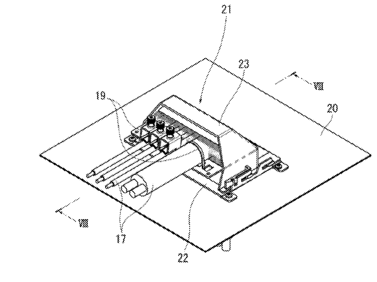
  • Cable holding tool
  • Cable holding tool
  • Cable holding tool

Examples


Embodiment Construction

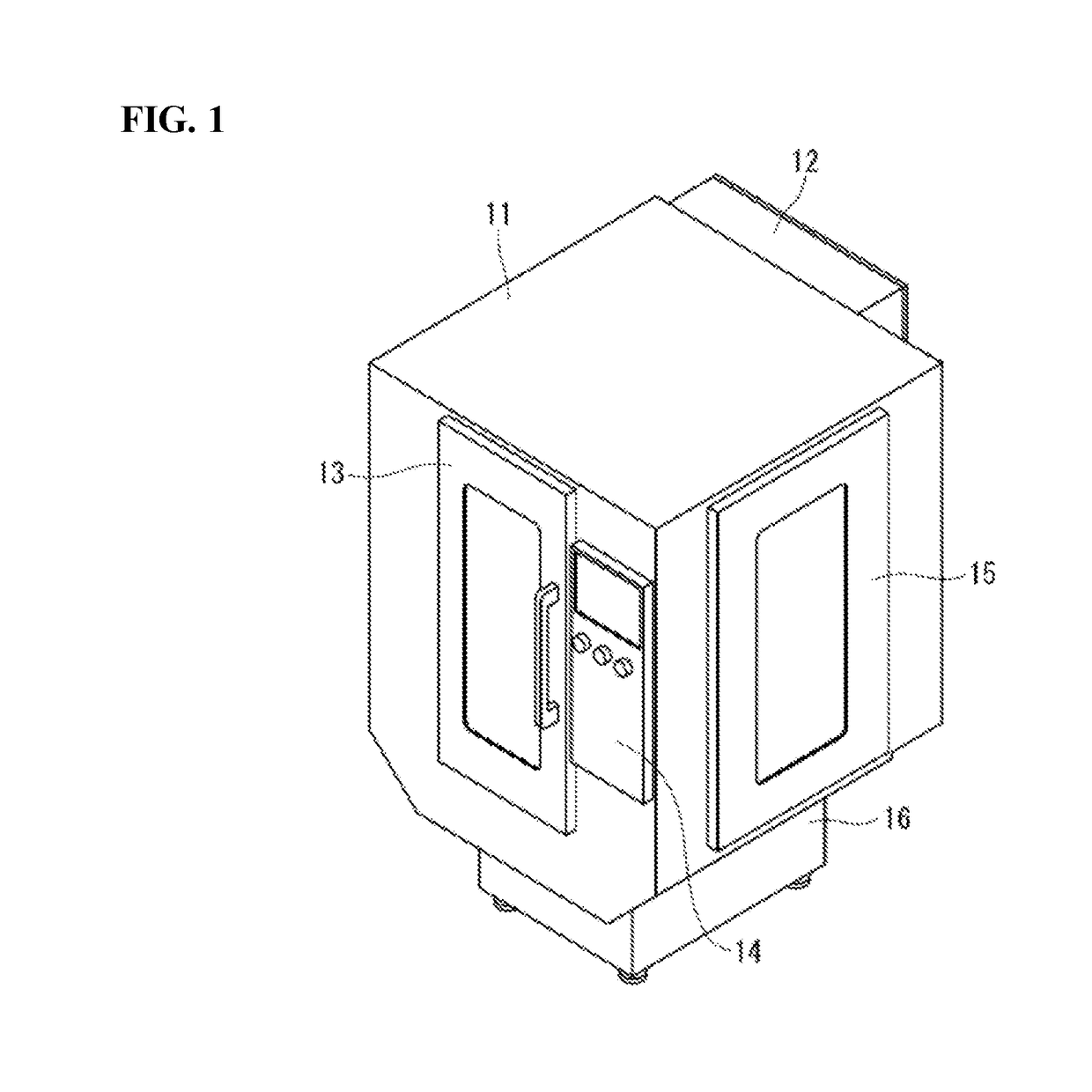
[0020]A first embodiment of a cable holding tool of the present invention is described based on the attached drawings below. FIG. 1 shows a perspective view of a front surface side of a working machine to which the cable holding tool of the present embodiment is attached. The working machine includes a workshop 11 housing processing machinery for machining workpieces, and a control room 12 housing control devices for controlling the processing machinery. The control room 12 is attached to a back surface of the workshop 11. Note that in FIG. 1, the reference numeral 13 represents a door for inserting and removing the workpieces, the reference numeral 14 represents an operation panel, the reference numeral 15 represents an inspection opening, and the reference numeral 16 represents a coolant tank.

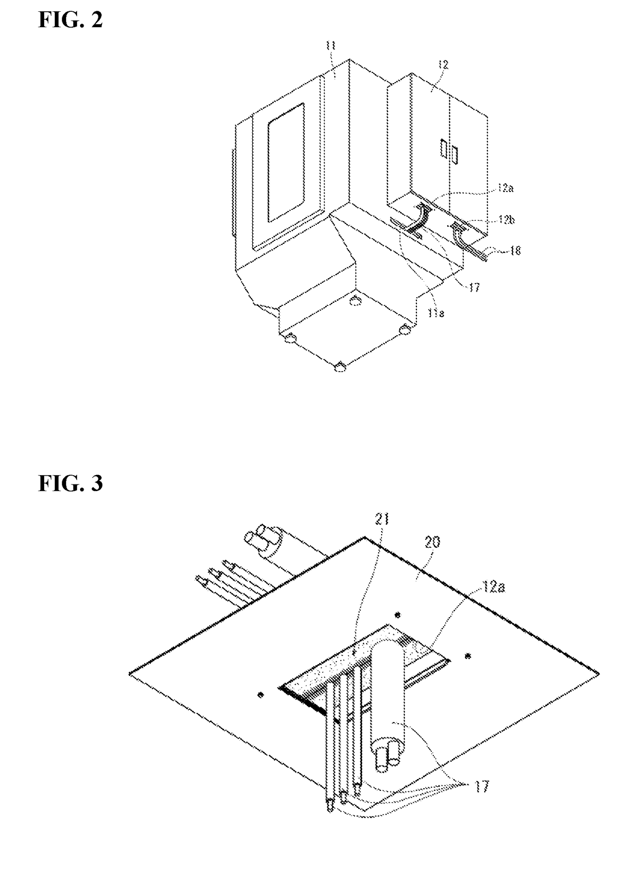
[0021]FIG. 2 shows a perspective view of a back surface side of the working machine. The processing machinery in the workshop 11 and the control devices in the control room 12 are connected b...


PUM


Abstract

Provided is a cable holding tool capable of reducing a size of a gap formed at a portion where soft members sandwich a cable to thereby increase air-tightness thereat. First sealing members (26a, 26b) having fluffs are attached to a first opposing surface of a soft member (25). Second sealing members (29a, 29b) having fluffs are attached to second opposing surfaces of soft members (28a, 28b). When a cable (17) is sandwiched between the first sealing members (26a, 26b) and the second sealing members (29a, 29b), the fluffs of the first sealing members (26a, 26b) and the fluffs of the second sealing members (29a, 29b) are in contact with each other.

Description

TECHNICAL FIELD[0001]The present invention relates to a cable holding tool for holding a cable which passes through a wiring opening.BACKGROUND ART[0002]A working machine includes, for example, a workshop for machining workpieces using tools such as drills and milling cutters, and a control room for controlling processing machinery in the workshop. Control devices such as a driver and a computer are housed in the control room. The processing machinery and the control devices are connected by cables. A wiring opening is opened in a housing of the control room to allow the passage of the cables. A cable holding tool that functions to hold the cables and also functions to block outside air is attached to the housing of the control room. The working machine is arranged inside a factory. Air inside the factory contains dust, oil, coolant fluids, or the like. When the air containing these matters enters the control room, they cause malfunctioning of the control devices. Therefore, the cab...

Claims


Application Information

Patent Timeline
IPC IPC(8): H02G3/22H02G3/04
CPCH02G3/0406H02G3/22H05K7/00H02G3/185H02G3/32
Inventor SUGASAWARA, JUNKUBOTA, HARUNOBUTAKINO, TOSHIO
Owner SUGATSUNE IND CO LTD
Learn More