Connector case

Active Publication Date: 2007-04-05
DENSO CORP
View PDF6 Cites 12 Cited by
  • Summary
  • Abstract
  • Description
  • Claims
  • Application Information

AI Technical Summary

Benefits of technology

[0011] It is an object of the present invention to provide a connector case with an improved airtightness of the inside of the connector case.
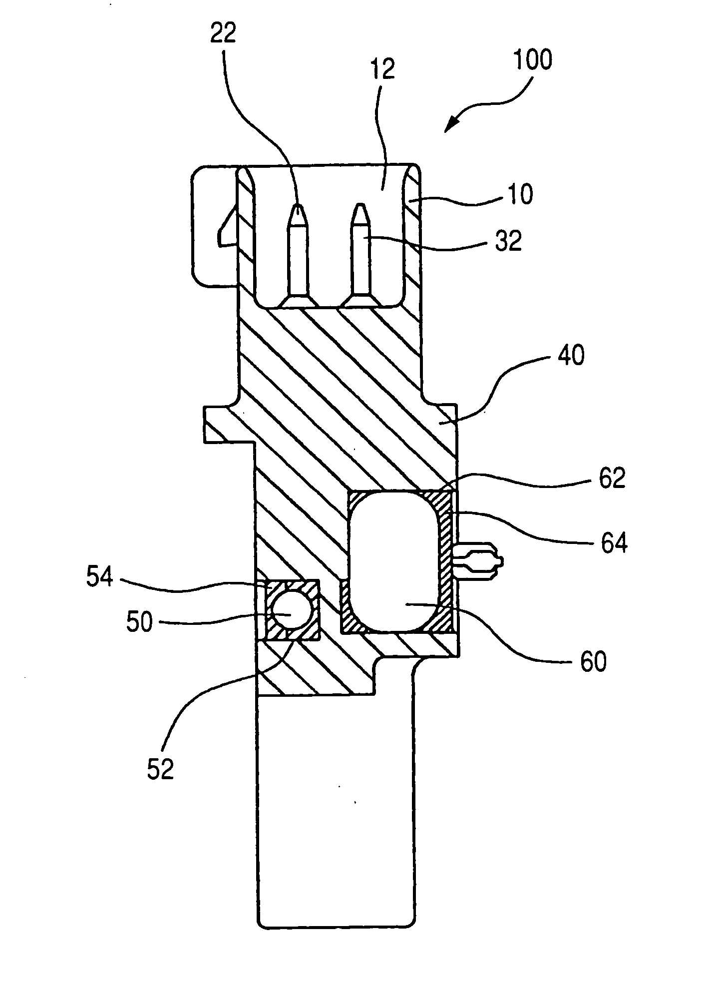
[0013] Thus, the middle part, between the external connection part and the resin case terminal, inserted in the resin case, is exposed in the resin injection part of a concave shape formed in the resin case. The resin injection part and the middle part of the terminal are filled with an encapsulating resin. The surface of the middle part is thereby sealed completely with the encapsulating resin. Accordingly, even if a crack or a small gap is generated between the resin case terminal and the resin case, it is possible to prevent extending such a crack or a small gap to the connector part through the terminal by the presence of the encapsulating resin in the resin injection part, and thereby possible to increase the air tightness of the connector part in the connector case.
[0014] Further, it is preferred to form the terminal consisting of the external connection terminal, the middle part, and the resin case terminal with a single electrode member. Accordingly, even if a crack or a small gap is generated between the resin case terminal and the resin case, it is possible to prevent completely extending such a crack or a small gap to the connector part through the terminal by the presence of the encapsulating resin and the middle part placed in the resin injection part of the resin case.
[0015] Still further, it is preferred to form the terminal consisting of the external connection terminal, the middle part, and the resin case terminal with at least two electrode members and preferred that the divided electrode members are electrically connected at the middle part of the terminal placed in the resin injection part of the resin case. Accordingly, because the middle part of the terminal is exposed in the resin injection part of the resin case, it is possible to easily form the terminal with two electrode members and to electrically connect the two electrode members at the exposed middle part in the resin injection part, and also to prevent extending such a crack or a small gap generated between the terminal and the resin case at the middle part of the terminal by the presence of the encapsulating resin.
[0016] Still further, it is preferred to form the resin injection parts in both a front surface and a back surface of the resin case, and to expose the middle part of the terminal in the resin injection parts of both the front surface and the back surface of the resin case. Accordingly, the two faces of the middle part of the terminal are exposed in opposite directions and the resin injection parts in both surfaces are filled with an encapsulating resin, even if a crack or a small gap is generated between the resin case terminal and the resin case, it is possible to prevent extending such a crack or a small gap to the connector part through the terminal by the presence of the encapsulating resin in both the surfaces of the resin case, and thereby possible to increase the air tightness of the connector part.
[0017] Moreover, it is preferred to insert an electric element capable of absorbing electromagnetic noises input into the external connection terminal in the resin injection part of the resin case, and preferred that the resin injection part accommodating both the middle part of the terminal and the electric element is completely filled with the encapsulating resin. Further, it is preferred to mount such a resin case on a vehicle alternator, and to insert a capacitance (as a surge absorber) for absorbing surge generated at output terminals of the vehicle alternator into the resin injection part, and preferred that the resin injection part accommodating the middle part of the terminal and a capacitor element is filled with the encapsulating resin. Accordingly, it is possible to increase the degree of airtightness of the connector part in the connector case without increasing design cost and manufacturing cost only by changing the design of the connector case so that the middle part of the terminal is exposed into the resin injection part of a concave part in the resin case into which the electric element and the capacitor element are inserted, placed, and filled with the encapsulating resin.

Problems solved by technology

Recently, the mounting space for a vehicle alternator becomes more and more limited because of reduction of an engine-mounting space in a vehicle caused by a tendency of slant-nose at a front part of a vehicle for reducing running resistance of a vehicle such as air resistance and needs to enlarge a vehicle compartment space.
Thus, the mounting environment for the vehicle alternator is deteriorating according to the various needs and demands of the vehicle technologies.
However, it is difficult to adhere closely resin with insert-molded terminals in an encapsulating resin case for a voltage regulator placed in the vehicle alternator.
For example, even if the resin adheres closely with the insert-molded terminals during a manufacturing process, a crack or a small gap is easily generated between the resin and the insert-molded terminals by heat stress and heat expansion in thermal cycle operation of an internal combustion engine mounted on the vehicle during usual running of the vehicle because of different coefficients of thermal expansion of them and others.
When end parts of the metal terminals are exposed to the outside of the encapsulating resin case, through such a crack or a small gap, water or moisture is entered into the inside of the encapsulating resin case, and in the worst case, the water or moisture reaches to the inside of the connector part through the terminal, and the airtightness of the encapsulating resin case is deteriorated.

Method used


Image

  • Connector case
  • Connector case
  • Connector case

Examples


embodiment

[0025] A description will be given of a connector case to which the concept of the present invention is adopted with reference to drawings.

[0026]FIG. 1 is a front view of a connector case 100 before performing an encapsulating mold process for injecting an encapsulating resin into a resin injection part 52 of a concave shape in a resin case according to a preferred embodiment of the present invention. FIG. 2 is a back view of the connector case 100 shown in FIG. 1 before performing the encapsulating mold process of injecting an encapsulating resin into another resin injection part 62 of a concave shape in the resin case. FIG. 3 is a front view of the connector case 100 after the completion of the encapsulating mold process of injecting the encapsulating resin 54 into the resin injection part 52 of the resin case. FIG. 4 is a back view of the connector case 100 shown in FIG. 3 after the completion of the encapsulating mold process of injecting the encapsulating resin 64 into the res...


PUM


Abstract

A connector case has a connector part, a terminal, and a resin case. The connector part of a concave shape accommodates external connection terminals. One end of the terminal is the external connection terminal. The terminal is inserted in the resin case by insert molding. The connector part, the terminal, and the resin case are integrated in one body. A part of the terminal other than the external connection terminal is exposed to the outside of the resin case as a resin case terminal. The resin case has a resin injection part of a concave shape accommodating a middle part of the terminal between the external connection terminal and the resin case terminal, namely, the middle part is exposed in the resin injection part and is filled with an encapsulating resin completely.

Description

CROSS-REFERENCE TO RELATED APPLICATIONS [0001] This application is related to and claims priority from Japanese Patent Application No. 2005-261457 filed on Sep. 9, 2005, the contents of which are hereby incorporated by reference. BACKGROUND OF THE INVENTION [0002] 1. Field of the Invention [0003] The present invention generally relates to a connector case with an improved airtightness consisting of a female connector, to be jointed to a male connector, mounted on a vehicle alternator. [0004] 2. Description of the Related Art [0005] Recently, the mounting space for a vehicle alternator becomes more and more limited because of reduction of an engine-mounting space in a vehicle caused by a tendency of slant-nose at a front part of a vehicle for reducing running resistance of a vehicle such as air resistance and needs to enlarge a vehicle compartment space. For such reasons, the vehicle alternator is mounted on a bottom side of the vehicle or piping of a reservoir tank, a brake fluid ta...

Claims


Application Information

Patent Timeline
IPC IPC(8): H01R13/66
CPCH01R13/665H01R43/24Y10S439/936
Inventor KURAHASHI, TAKAAKI
Owner DENSO CORP
Why Eureka
Try Eureka