Structore of molding tools, injection molding device, and molding method

Inactive Publication Date: 2010-08-05
KONICA MINOLTA OPTO
View PDF8 Cites 1 Cited by
  • Summary
  • Abstract
  • Description
  • Claims
  • Application Information

AI Technical Summary

Benefits of technology

[0004]Accordingly, an object of the present invention is to offer structures of molding tools and injection molding devices, being easily able to mold the optical element, even though the resin exhibiting low viscosity is used, whereby adverse influence caused by air can be suppressed.
[0020]Concerning the above described injection molding device, the structure of the molding tools is effective for the injection device which uses the resin exhibiting low viscosity. Accordingly, leakage of the resin and air trapping into the resin are effectively prevented, whereby the above described injection molding device can effectively and accurately produce the molded product.

Problems solved by technology

Concerning the above described injection molding device, if a resin exhibiting low viscosity is injected during the injection operation, said resin tends to leak outside through the clearance between the molding tools, so that molding pressure cannot be increased.
Further, if the molding is conducted in the air, air tends to be trapped in the resin, so that the resin is prevented from being hardened, or the resin is unevenly hardened, which are major problems.

Method used


Image

  • Structore of molding tools, injection molding device, and molding method
  • Structore of molding tools, injection molding device, and molding method
  • Structore of molding tools, injection molding device, and molding method

Examples


Embodiment Construction

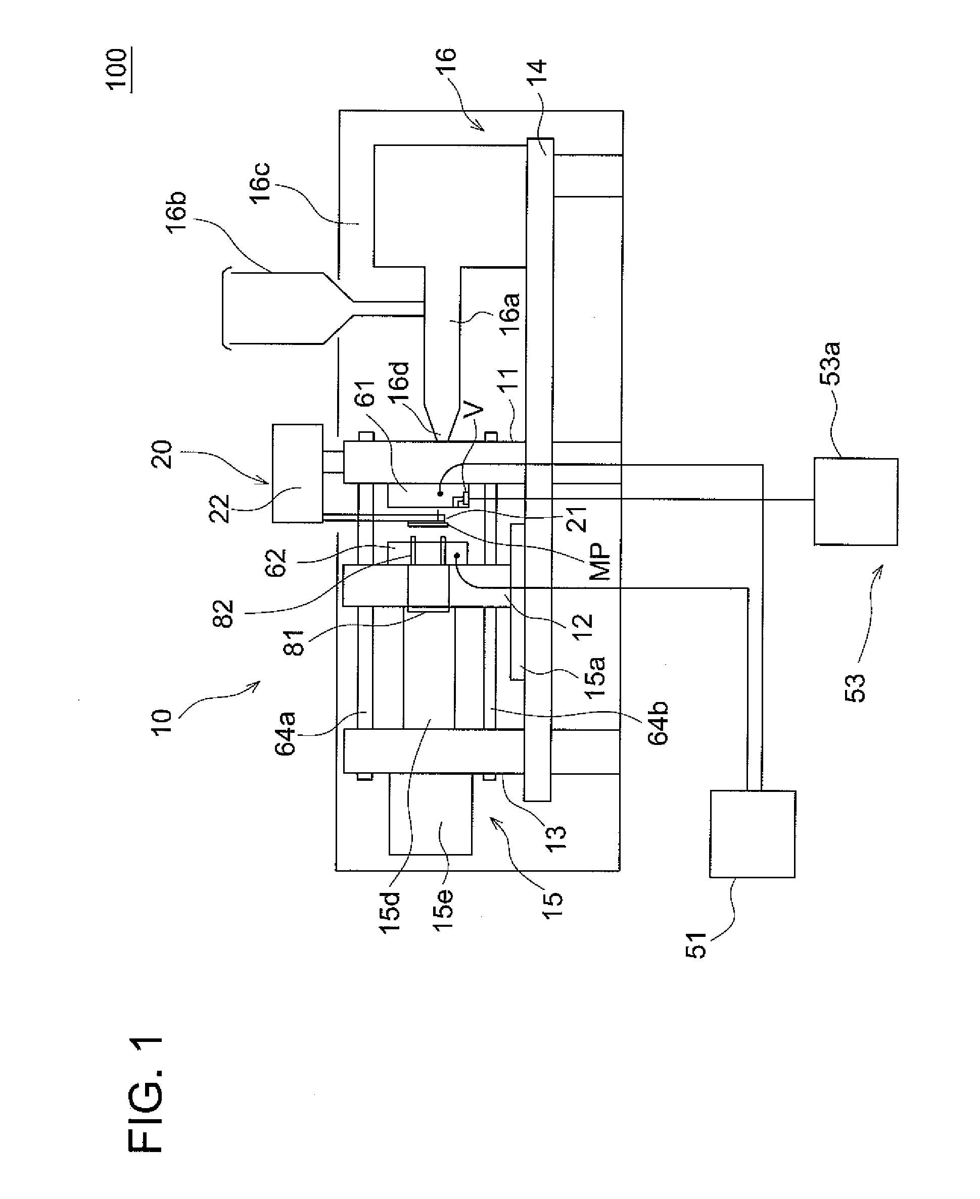
[0046]An injection molding device and a molding method, being embodiments of the present invention, will now be detailed while referring to the drawings. FIG. 1 is a front view showing a schematic structure of the injection molding device.

[0047]Injection molding device 100 of the present invention includes injection molding machine 10, take-out device 20, temperature control device 51, and pressure decreasing device 53. Injection molding machine 10 produces molded product MP by the injection, take-out device 20 is a section from which molded product MP is taken out, temperature control device 51 controls the temperature of molding tools 61 and 62 of injection molding machine 10, and pressure decreasing device 53 is a section to conduct vacuum drawing from the engaged molding tools. The molding tools are opened or closed horizontally in injection molding device 100.

[0048]Injection molding machine 10 includes fixed plate 11, movable plate 12, tool clamping device 13, molding tool open...


PUM

PropertyMeasurementUnit
Moldableaaaaaaaaaa

Abstract

Provided are a structure of molding tools and an injection molding device that can easily perform molding of an optical element even from a resin of low velocity or the like and can suppress any negative effects by air. The structure of the molding tools includes between the molding tools (61, 62) a fixed molding tool (61) and a movable molding tool (62) and an O-ring (63a) for keeping air tightness and a resin seal (63b) for preventing any resin leakage. The O-ring (63a) performs decreasing of the pressure in a cavity (CV) formed by joining the molding tools (61, 62), whereby the vacuum molding in which resin supply and resin curing is carried out under a decreased pressure can be performed. Accordingly, the effects such as prevention of air bubbling due to air trapping by injected resin within the cavity (CV) can be attained. Furthermore, the resin seal (63b) can prevent any resin leakage from the molding tools (61, 62) even when the resin having a low viscosity is used.

Description

TECHNICAL FIELD[0001]The present invention relates to a molding technology of an optical element, and in particular, to structures of molding tools, injection molding devices, and molding methods, for molding the optical element, using an energy curable resin.BACKGROUND OF THE INVENTION[0002]An injection molding device is disclosed (in Patent Document 1), in which a fixed molding tool and a movable molding tool are sandwiched between a fixed plate and a movable plate. This injection molding device includes a toggle mechanism for driving the movable plate, said toggle mechanism tightens the fixed plate and the movable plate, whereby the fixed molding tool and the movable molding tool are engaged to each other. When resins are injected by this device, a cavity formed by both tools allows air to be ejected through clearances between both tools.Patent Document 1: Unexamined Japanese Patent Application Publication 7-68,610DISCLOSURE OF THE INVENTIONProblems to be Solved by the Present In...

Claims


Application Information

Patent Timeline
IPC IPC(8): B29C45/63B29C45/28
CPCB29C45/1701B29D11/00B29C2791/006B29C45/2608
Inventor MIYAZAKI, TAKEMIHOSOE, SHIGERUFUJII, YUITI
Owner KONICA MINOLTA OPTO
Why Eureka
Try Eureka