Assembly of saw handle and saw member

a technology of saw handle and saw blade, which is applied in the field ofsaw, can solve the problems of user inconvenience and complicated assembly of conventional saws, and achieve the effect of convenient and fast replacemen

Inactive Publication Date: 2017-03-30
WANG KUANG PIN
View PDF13 Cites 2 Cited by
  • Summary
  • Abstract
  • Description
  • Claims
  • Application Information

AI Technical Summary

Benefits of technology

[0007]One object of the present invention is to provide an assembly of saw handle

Problems solved by technology

The assembling of the conventional saw is compl

Method used


Image

  • Assembly of saw handle and saw member
  • Assembly of saw handle and saw member
  • Assembly of saw handle and saw member

Examples


Embodiment Construction

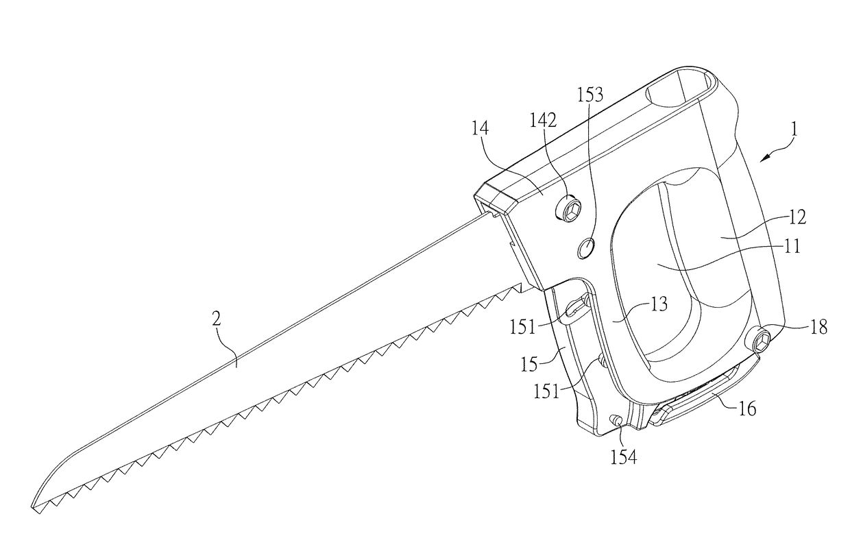
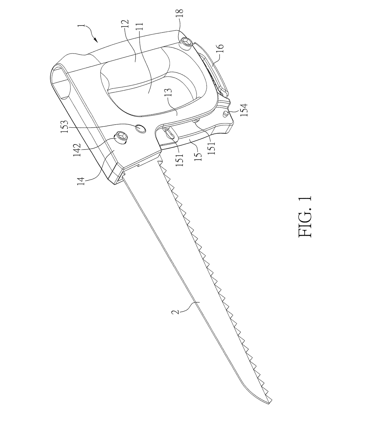
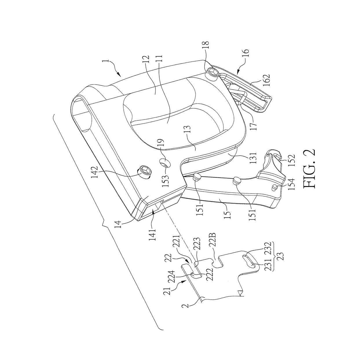
[0022]Please refer to FIGS. 1 to 7, illustrating an assembly of saw handle and saw member according to a first embodiment of the present invention. The embodiments are provided for illustrative purposes, and the claimed scope of the present invention is not limited thereto.

[0023]As shown in FIGS. 1 to 2, an assembly of saw handle and saw member comprises a saw handle 1 and a saw member 2. Specifically, as shown in FIGS. 1 and 2, the saw handle 1 has an elongate handle hole 11. A handle portion 12 and a guard portion 13 are respectively defined at two sides of the handle hole 11 along the width direction of the handle hole 11, and the guard portion 13 is spaced from to the handle portion 12. An inserting portion 14 and a fixing device are respectively disposed at two ends of the saw handle 1 along the length direction of the handle hole 11. A swing arm 15 is pivoted on the saw handle 1, and the swing arm 15 and the guard portion 13 are located at the same side of the saw handle 1. Th...


PUM

PropertyMeasurementUnit
Timeaaaaaaaaaa
Diameteraaaaaaaaaa
Lengthaaaaaaaaaa

Abstract

An assembly of saw handle and saw member is provided. An end portion of the saw member is inserted into an inserting groove of the saw handle. The saw handle has stopping bars at an inserting portion and a swing arm. The end portion defines an opened hole and a closed hole. When the swing arm is moved to an eject position and not received in a receiving space of a guard portion of the saw handle, the saw member is not blocked by the swing arm and is allowed to be inserted into the inserting groove. After the saw member is inserted into the inserting groove and the swing arm is moved to a fix position, the stopping bars are respectively located in the opened hole and the closed hole, so that the saw member can be assembled with the saw handle in a convenient and rapid manner.

Description

BACKGROUND OF THE INVENTION[0001]1. Field of the Invention[0002]The present invention relates to a saw, and more particularly to an assembly of saw handle and saw member.[0003]2. Description of the Prior Art[0004]FIG. 12 illustrates a sectional view of a conventional saw. The saw includes a saw handle 91, a fastening bracket 92, and a saw member 93. An inserting groove 911 is laterally opened on the saw handle 91, the fastening bracket 92 has an end portion 921 corresponding to the inserting groove 911, and the fastening bracket 92 further has an assembling portion 922 for fixing the saw member 93. In assembling, firstly the saw member 93 is assembled with the assembling portion 922 of the fastening bracket 92, and then the end portion 921 of the fastening bracket 92 is inserted into the inserting groove 911, next the fastening bracket 92 and the saw handle 91 are fastened with each other by a screw 94, so that the saw can be assembled for further use.[0005]However, the fastening br...

Claims


Application Information

Patent Timeline
IPC IPC(8): B23D51/10B27B21/04B25G3/12B23D51/01
CPCB23D51/10B25G3/12B27B21/04B23D51/01B23D49/10B23D49/12B23D49/14B23D61/123B25G3/18
Inventor WANG, KUANG PIN
Owner WANG KUANG PIN
Why Eureka
Try Eureka