Pipe cutting and beveling machine

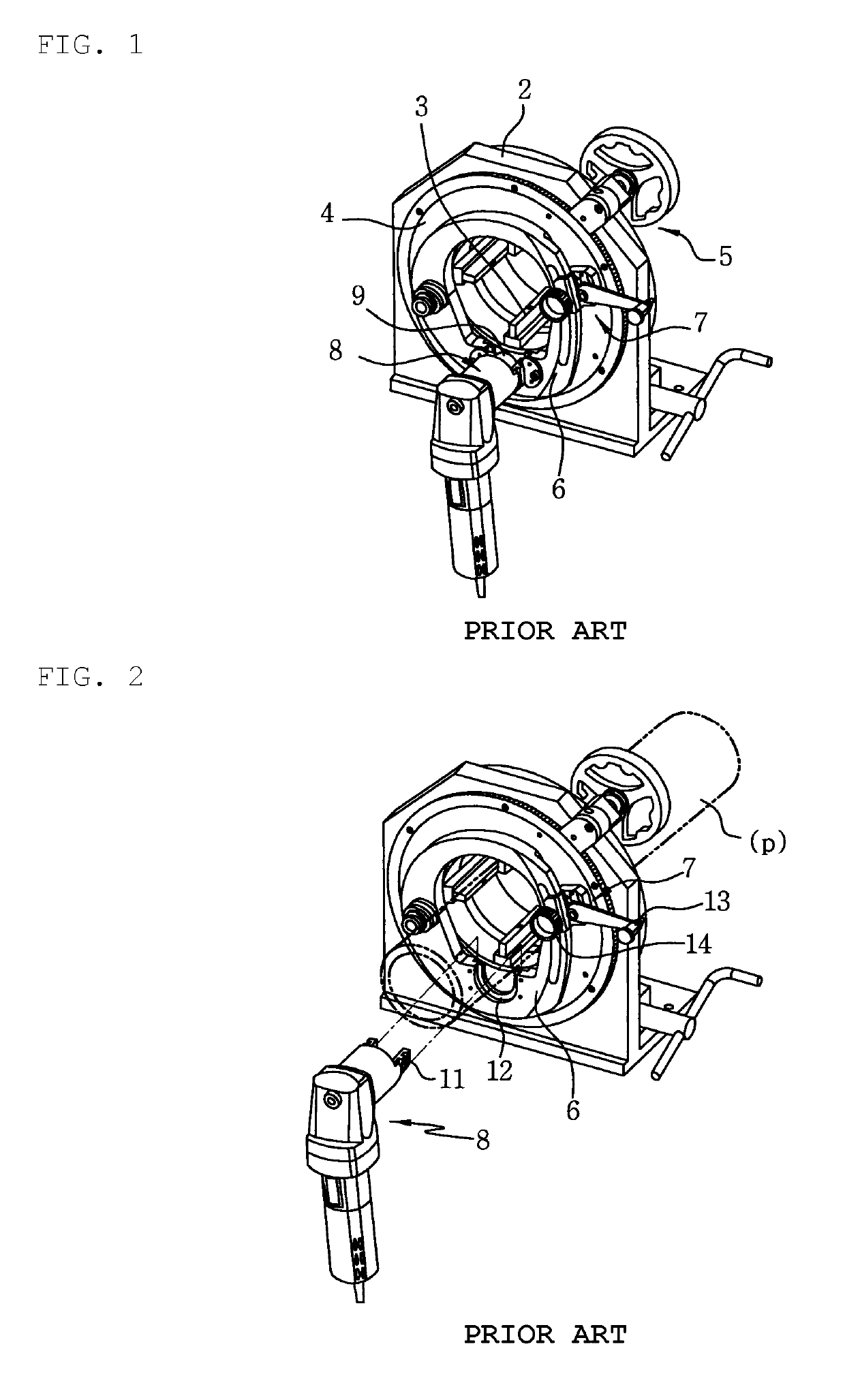
a beveling machine and pipe technology, applied in the field of pipe cutting and beveling machines, can solve the problems of lowering work efficiency and productivity, pipe p affecting the lifting of the cutter unit, and affecting the quality of pipe cutting, etc., and achieves the effects of convenient and fast replacement, fine adjustment, and simple structur

Active Publication Date: 2019-11-05
DCSENG CO LTD
View PDF27 Cites 0 Cited by
  • Summary
  • Abstract
  • Description
  • Claims
  • Application Information

AI Technical Summary

Benefits of technology

[0023]Since the pipe cutting and beveling machine according to the present disclosure has a structure in which the cutter unit is tilted laterally, there is an advantage in that the cutting blade can be conveniently and quickly replaced without interfering with the pipe even if the pipe is mounted.
[0024]In addition, there are advantages in that the entry control unit configured to enter or retract the cutter unit in order to cut the pipe has a simple structure in which restraint can be easily released by the action of lifting the lever in the axial direction and the pipe can be restrained again by elastic lowering by releasing the lever again, and in that the entry and retreat actions of the cuter unit can be finely adjusted.
[0025]In addition, since the entry adjustment plate has a structure which can be applied with a preload, no clearance is generated in the entry adjustment plate, and thus vibration is not generated in the cutting blade, which enables high quality pipe cutting and beveling.
[0026]Further, the piping cutting and beveling machine according to the present disclosure has an advantage in that it further includes a beveling stopper that can be rotated toward the cut surface of the pipe, so that during the beveling operation, the cut surface of the pipe can be accurately aligned with the beveling blade.

Problems solved by technology

However, the cutter unit mounting structure described above has no problem in the standby state or in the state of preparing pipe cutting, but has a serious inconvenience in that it is necessary to remove the cutter unit in order to replace the cutting blade or the chamfering blade.
However, since the pipe p is fixed to the central portion of the rotary plate, the pipe p interferes with lifting the cutter unit 6.
Therefore, in order to replace the cutting blade or the chamfering blade in the course of performing a work or in order to perform other work, it is necessary to remove the cutter unit in order to replace the cutting blade or the chamfering blade, which leads to a problem that the work efficiency and productivity are lowered.
On the other hand, there are problems in that the entry control unit 7 configured to cause the cutter unit 8 to enter or retreat to or from the pipe p side is not finely tuned after setting, that there occurs a phenomenon in which the entry adjustment plate 6 is slipped by the cutting load of the cutter unit 8, and that the proper fastening pressure of the entry adjustment plate 6 is not adjusted, and thus serious vibration is generated by the cutting blade.
However, when there is an error in setting, it cannot be corrected in the set state, and it is necessary to perform the setting from the beginning again.
That is, when a large clearance is generated, a serious vibration is applied to the cutter unit 8 during operation, which significantly reduces the lifespans of equipment and the machining tools.
When there is little clearance, a problem occurs in that the entry adjustment plate 6 cannot be controlled.
However, a device capable of adjusting such a clearance has not been developed so far.

Method used


Image

  • Pipe cutting and beveling machine
  • Pipe cutting and beveling machine
  • Pipe cutting and beveling machine

Examples


Embodiment Construction

Technical Problem

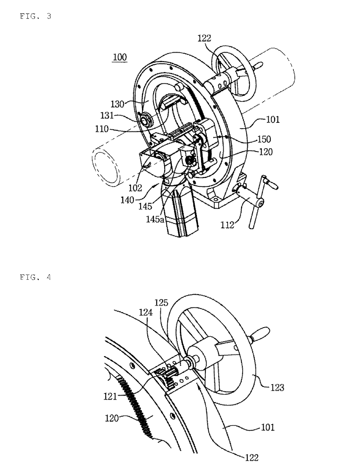
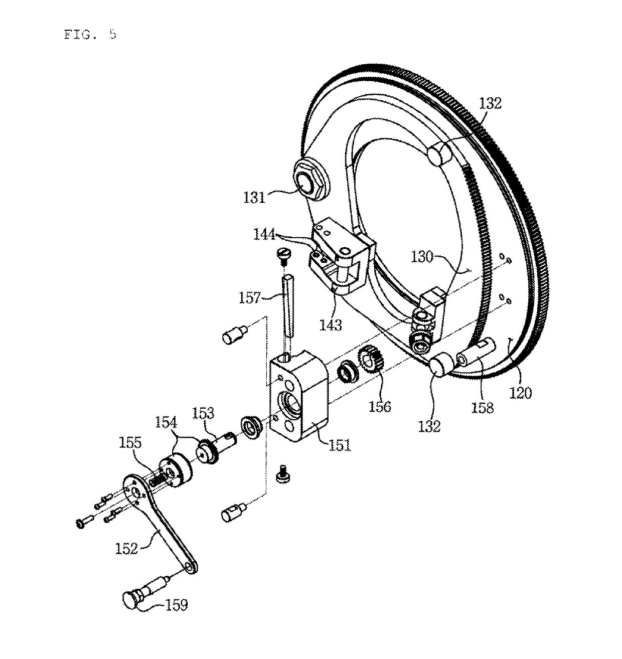
[0013]The present disclosure has been made to solve the above problems, and an aspect of the present disclosure is to provide a pipe cutting and beveling apparatus in which a cutter unit is configured to be tilted to one side in the state of being fixed on an entry adjustment plate, so that a cutting blade or a chamfering blade can be easily and quickly replaced without separating the cutter unit to the outside of the machine and further without removing the pipe even in the state where the pipe is fixed to the machine chamfered blade.

[0014]In addition, another aspect of the present disclosure is to provide a pipe cutting and beveling machine capable of easily restraining and releasing an entry adjustment plate while making it possible to finely adjust entry and retreat intervals of an entry control unit configured to cause the cutter unit to enter toward or retreat from the pipe side.

[0015]Further, another aspect of the present disclosure is to provide a pipe cutti...


PUM

PropertyMeasurementUnit
movementsaaaaaaaaaa
depthaaaaaaaaaa
workabilityaaaaaaaaaa

Abstract

A machine for cutting or beveling a pipe. A cutter unit rotates around the pipe while cutting any surface of the pipe after gripping and fixing the pipe. The machine includes: a main body which a pipe passes through the center portion thereof to be fixed; and a cutter unit coupled to the main body unit rotates around the fixed pipe to cut or bevel the pipe. The cutter unit may have a rotating unit on one side to pull the cutter unit aside and a locking unit on the other side to restrain or release the cutter unit. An entry control unit operating the cutter unit includes: a lever gear-engaged with an outer side surface of an entry control plate; and a clutch formed on a rotation shaft of the lever such that the restraint is released when the lever is lifted or pressed in the axial direction.

Description

CROSS REFERENCE TO RELATED APPLICATIONS[0001]This application is the U.S. National Phase Application of PCT / KR2017 / 003522, filed Mar. 30, 2017, which claims priority to Korean Patent Applications 10-2016-0040024, filed Apr. 1, 2016 and 10-2016-0086348, filed Jul. 7, 2016.TECHNICAL FIELD[0002]The present disclosure relates to a machine capable of cutting or beveling a pipe, a circular pipe material, a rod material, or the like, by fixedly fastening the pipe, and then causing a cutter unit to turn around the pipe while cutting one surface of the pipe.BACKGROUND ART[0003]In the piping facility industry, the technique of cutting a pipe or cutting and then beveling a pipe is one of the processes as important as a welding technique. In the past, gas cutting machines, saw machines and the like were used for pipe cutting and beveling. However, in recent years, as dedicated machines have been distributed, quality, workability, and productivity have been improved.[0004]As illustrated in FIG. ...

Claims


Application Information

Patent Timeline
Patent Type & Authority Patents(United States)
IPC IPC(8): B23C3/12B26D7/26B26D7/20B23Q9/00B23D33/02B26D7/02B23B5/16B26D3/16B23D21/04B23P23/02B23Q9/02B23C1/12
CPCB23D21/04B23C3/122B23Q9/0035B23B5/163B26D3/16B26D7/02B23P23/02B23C1/12B23C3/12B26D7/20B26D7/265B26D7/26B23D33/02Y10T82/22Y10T409/308512Y10T409/30644Y10T29/5199B23B2215/72Y10T409/304144B26D3/166B26D3/02
Inventor CHOI, INSUNG
Owner DCSENG CO LTD
Why Eureka
Try Eureka