Ultra-High-Pressure Fluid Injection Dynamic Orbit-Transfer System and Method

Inactive Publication Date: 2017-03-30
HONG RUIQING
View PDF70 Cites 1 Cited by
  • Summary
  • Abstract
  • Description
  • Claims
  • Application Information

AI Technical Summary

Benefits of technology

The patent text describes a system and method for assisting an aircraft to transfer orbits efficiently using ultra-high-pressure fluid injection. This system aims to minimize the number of physical apparatuses used and to reduce the chance of damage to mechanical components, ultimately improving safety performance and allowing for effective and efficient transfer of orbits.

Problems solved by technology

The exterior of the existing space shuttles, space aircrafts and aviation aircrafts all have their intrinsic design flaws which require installation of a wide variety of auxiliary equipment and devices, and make the overall design of the aircraft become more complicated and difficult to operate.
Moreover, the aircrafts, due to the presence of the auxiliary equipment and devices, are heavy in weight therefore low in energy efficiency.
The exterior design of space shuttles has a major aerodynamic flaw.
This high-thrust rocket requires the use of enormous amount of energy.
Furthermore, since all the mechanical structures of an aircraft or flying objects are very complicated, they may to undesirably interfere with each other.
This increases the chance that any one of the mechanical components is damaged by the others.
Moreover, the more complex a mechanical structure is, the more difficult for it to be controlled, and the lower the safety performance of an aircraft will have.

Method used


Image

  • Ultra-High-Pressure Fluid Injection Dynamic Orbit-Transfer System and Method
  • Ultra-High-Pressure Fluid Injection Dynamic Orbit-Transfer System and Method
  • Ultra-High-Pressure Fluid Injection Dynamic Orbit-Transfer System and Method

Examples


Embodiment Construction

[0038]The following detailed description of the preferred embodiment is the preferred mode of carrying out the invention. The description is not to be taken in any limiting sense. It is presented for the purpose of illustrating the general principles of the present invention.

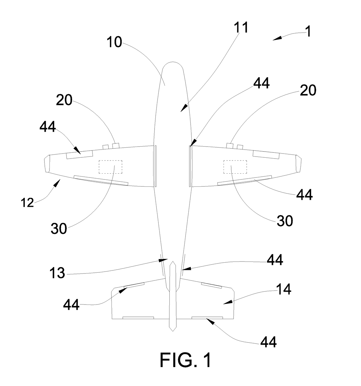
[0039]Referring to FIG. 1 to FIG. 3, FIG. 4A to FIG. 4B, FIG. 5A to FIG. 5C and FIG. 6 of the drawings, a flying object 1 according to a preferred embodiment of the present invention is illustrated. The flying object 1, such as an aircraft, may comprise a main body 10, an engine 20, a power system 30, and an ultra-high-pressure fluid injection dynamic orbit-transfer system 40.

[0040]The engine 20 may be supported in the main body 10 for providing a driving force for the main body to fly in the air or to move under water. The power system 30 may be supported in the main body 10 for providing power to the engine 20 and other components of the flying object 1.

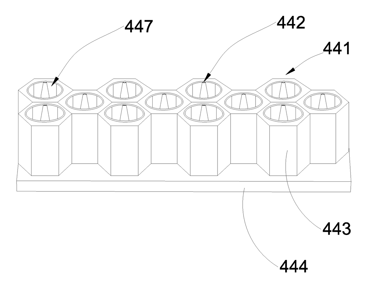
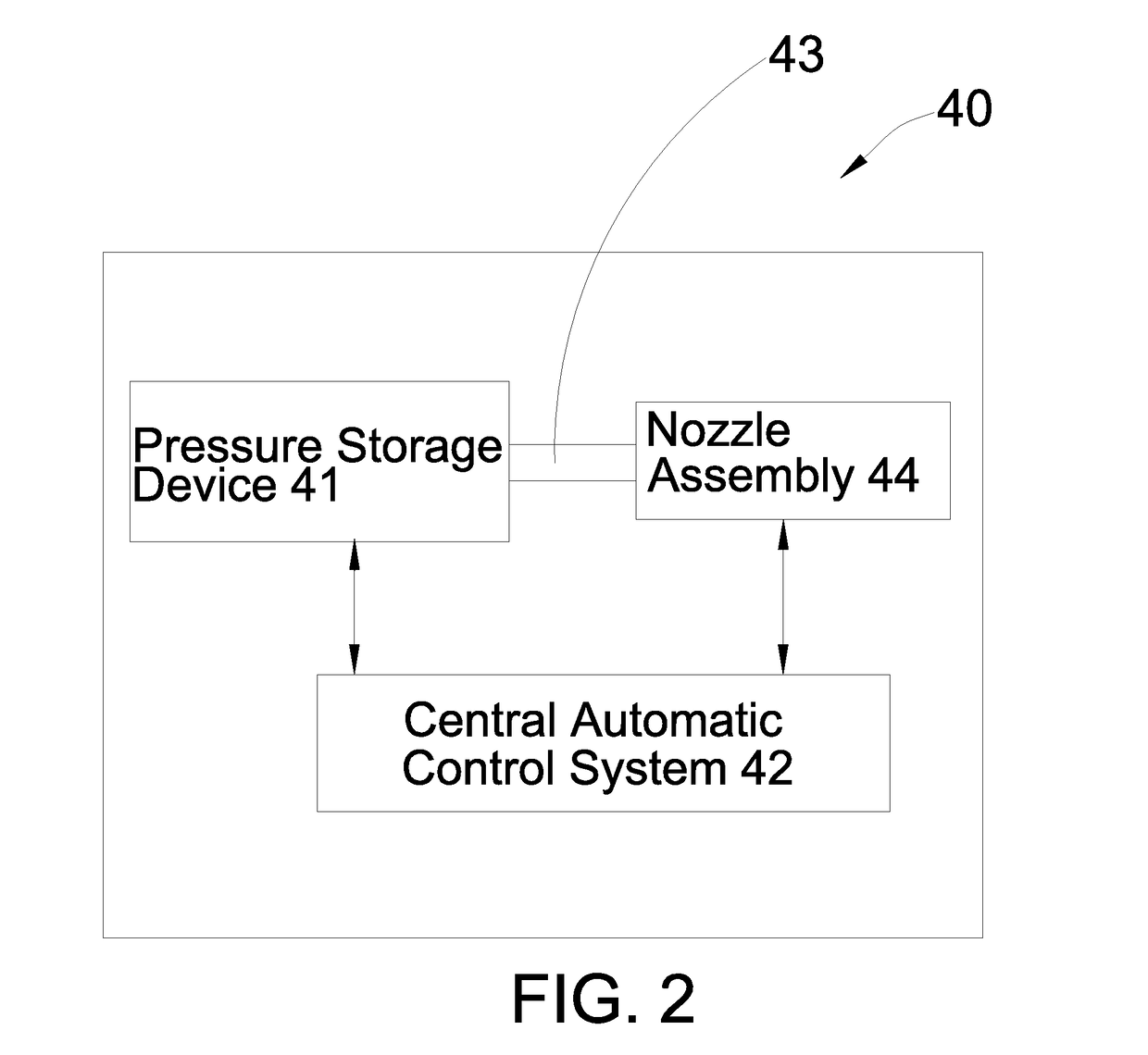
[0041]The ultra-high-pressure fluid injection dynamic orb...


PUM


Abstract

A flying object includes a main body, an engine, a power system and an ultra-high-pressure fluid injection dynamic orbit-transfer system which includes a pressure storage device for storing a predetermined amount of ultrahigh-pressure gas, a central automatic control system, at least one air pipeline connected to the pressure storage device, and a nozzle assembly provided on the main body and connected to the air pipeline. The nozzle assembly includes a plurality of nozzle units. Each of the nozzle units includes a nozzle body having a nozzle hole, and is arranged and aligned adjacent to at least another the nozzle unit. The central automatic control system is configured to selectively activate at least two of the nozzle units for ejection of ultrahigh-pressure gas so as to controllably alter a flying locus of the flying object.

Description

CROSS REFERENCES TO RELATED APPLICATIONS[0001]This is a Continuation-In-Part application of a non-provisional application having an application Ser. No. 14 / 004,166 and a filing date of Sep. 10, 2013, which is a national phase entry of application number PCT / CN2011 / 083309 and filing date Dec. 1, 2011. The content of these applications is incorporated by reference herewith.BACKGROUND OF THE PRESENT INVENTION[0002]Field of Invention[0003]The present invention relates to aeronautic and astronautic device technology, and more particularly to an ultra-high-pressure fluid injection dynamic orbit-transfer system and method used in a wide variety of flying objects.[0004]Description of Related Arts[0005]Objects in motion, whether they are space shuttles, aviation aircrafts, rockets, missiles flying in the sky, or moving objects sailing on water or moving underwater, will encounter resistance from air or water in the course of the flight or sailing, and will have a need to change its moving di...

Claims


Application Information

Patent Timeline
IPC IPC(8): B64C15/14
CPCB64C15/14B64C21/04Y02T50/10
Inventor HONG, RUIQING
Owner HONG RUIQING
Why Eureka
Try Eureka